TECHNICAL SPECIFICATIONS
Model PGF1RC Series
High Effi ciency 92+ AFUE Direct Vent or Non Direct Vent
Condensing Upfl ow/Horizontal Gas Furnace
M1200 Product Line

2

3
The high effi ciency upfl ow gas furnace may be installed free standing
in a utility room, basement, or enclosed in an alcove or closet. With
kit, it converts easily to horizontal application. The extended fl ush
jacket provides a pleasing “appliance appearance.” Design certifi ed
by the Canadian Standards Association (CSA). The product is truly
designed with the contractor and the consumer in mind.
Features and Benefi ts
– 100% fi red and tested — All units and each component (both mechanical
and electrical) are tested on the manufacturing line.
– Best packaging in the industry — Unique design assures product will
arrive to the homeowner dent free.
– Clean and quiet operation — Due to the unique design of in-shot burners,
location of inducer and use of insulation.
– Smart Start
®
state-of-the-art control board learns the start-up characteristics
of the furnace as installed in your home. It adapts to the most effi cient
start-up time extending the life of the igniter.
– Fixed 30 second blower delay at burner start-up assures a warm duct
temperature at furnace start-up. Adjustable blower off settings (60, 120,
160 and 180 seconds).
– Fixed 30-second post purge increases life of heat exchanger.
– Dependable, hot surface ignitor — Innovative application of an appliance
type ignitor with a 20-year history of reliability, assures no call-backs
because of handling.
– Color coded wire harness — Designed to fi t the components, all with
quick-connect fi ttings for ease of service and replacement.
– Tubular primary heat exchanger — Heavy gauge aluminized steel heat
exchanger assures a long life.
– Stainless steel secondary heat exchanger assures a long life.
– Fixed cooling cycle blower-off delay (TDR) increases cooling performance
when matched with a Maytag coil.
– Approved for direct vent furnace, category IV venting system – May
be vertically or horizontally vented using either a one-pipe or two-pipe
system for maximum fl exibility in installation.
– Fully insulated blower cabinet for quiet operation.
– Variable speed blower kit is available to maximize air conditioner and
heat pump effi ciencies. On selected units, SEER ratings up to 14 and HSPF
ratings up to 8.5 are ARI listed.
– Multi-speed direct drive blower — Designed to give a wide range of
cooling capacities. 40VA transformer included.
– LP convertible — Simple burner orifi ce and regulator spring change for
ease of convertibility.
– Factory installed drain system for reliable performance.
– Diagnostic light fl ashes identify limit failure, pressure switch failure and
improper ground and polarization — for easy troubleshooting.
– Incorporates integrated control board with connections for electronic
air cleaner, humidifi er and twinning.
– Two piece door design enhances furnace appearance and uses screw
fasteners for great fi t and accessibility.
– 3 amp fuse protection against low voltage shorts; protects transformer
and control board.
– Low voltage terminal board for easy fi eld wiring.
– Components and Controls — Designing quality into our products means
selecting manufacturers that have a reputation for delivering high quality,
dependable products.
• M1200 - 12 YEAR ALL PARTS
LIMITED WARRANTY
• M1200 WITH UPGRADED
WARRANTY PACKAGE -
12 YEAR ALL PARTS & LABOR
LIMITED WARRANTY
• Both the standard and
upgraded limited warranty
packages offer a 12 Year
Dependability Promise
to replace the entire unit, if the
unit’s major component (heat
exchanger or compressor)
fails within the fi rst 12 years
of operation, to the original
owner. All split system products
must be installed with a
matched indoor air handler
or indoor coil to qualify.
• Product registration (by
consumer or dealer) required
for 12-year Warranty and
Dependability Promise within
a limited period of time after
the installation. See current
warranty document for
details. This can be viewed at
www.maytaghvac.com or
ask your sales representative.
• Dealer is responsible for
registration of labor portion
of warranty.
• Also when registered,
this product is upgraded
to a limited lifetime heat
exchanger warranty.
4
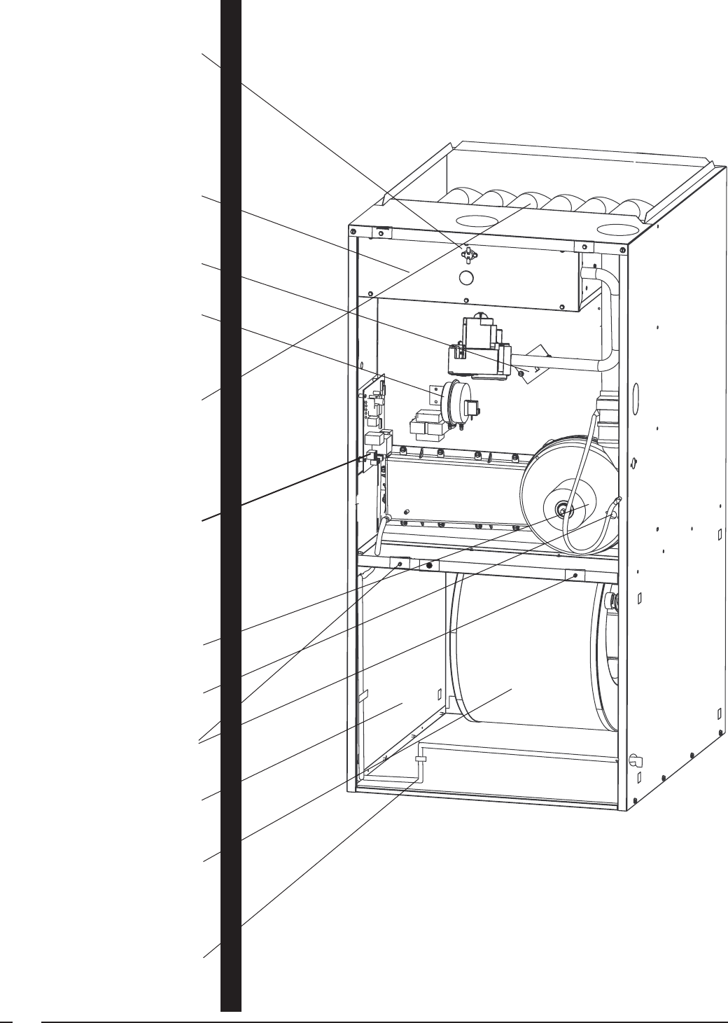
Roll-out Switch.
Remote Flame Sensor
for proof of carry-over.
(Not Shown)
Aluminized Steel In-shot
Burners, Hot Surface Ignitor
and Redundant Gas Valve
provide safe, reliable ignition
and effi cient combustion.
Supply Air Limit.
Pressure Switch assures
proper operation of the
induced draft system.
Counterfl ow Heat Exchanger
orientation and aluminized
steel tubular design, means
improved effi ciency and
durability.
SmartStart
TM
Integrated
Control monitors the burner
fl ame and limit circuit
continuously. Blower
timing has adjustable OFF
settings. Provides humidifi er
and electronic air cleaner
connections.
Induced Draft Blower provides
quiet and reliable operation.
Vent Switch protects against
blocked fl ue.
Front Door Screw Fasteners
ensure tight fi t.
Fully Insulated blower
compartment.
Multi-speed PSC Motor/
Blower provides quiet
airfl ow, reliable operation
and is installed on a slide
out track.
Factory Installed Drain
for reliable performance.
5
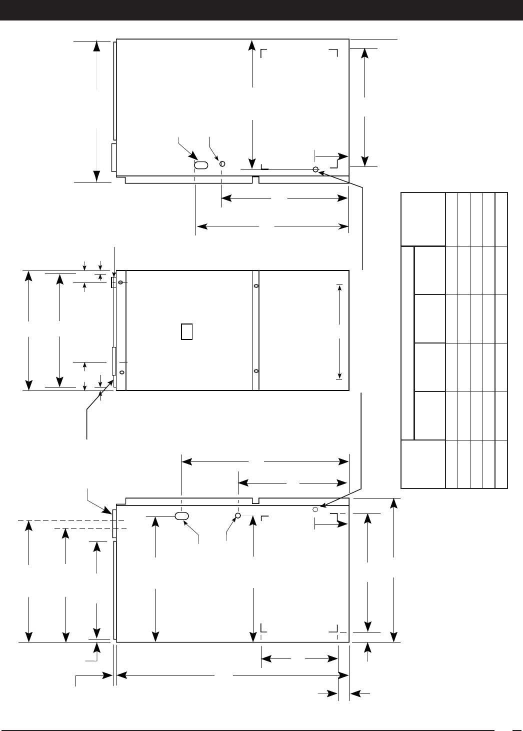
7/8" Dia. Electric
Connection
2 1/4"
23 1/4"
19 3/4"
3/4"
43"
25 1/8"
25 1/4"
23"
28"
15"
25 1/4"
33"
Return Air Opening
(Bottom)
Side Return
Bottom Return Opening
Condensate Drain Outlets
A
‡
B
‡
Combustion Air
Vent 3"
(See Fig. 15
for sizes)
1 1/2" x 3 1/2" Dia.
Opening for
Gas Connection
+
3/4"
3/4"
3/4"
22 1/2"
Exhaust Vent
Combustion Air
Inlet
1 1/2" x 3 1/2" Dia.
Opening for
Gas Connection
C
‡
2" PVC
Exhaust
Vent
(See Fig. 15
for sizes)
25 5/8"
20 1/2"
23"
+
7/8" Dia. Electric
Connection
30 1/4"
8"
8"
1 1/4"
1"
D
‡
27 5/8"
3”
DIMENSIONS
MODEL
NUMBER
PGF1RC
Dimensions
Shipping
Weights
(lbs)
A
(in.)
B
(in.)
C
(in.)
D
(in.)
40,000 A 14 1/4 12 3/4 5 1/8 11 3/4 133
60,000 A 14 1/4 12 3/4 5 1/8 11 3/4 140
80,000 B 19 3/4 18 1/4 7 7/8 17 1/4 172
100,000 B 19 3/4 18 1/4 7 7/8 17 1/4 180
120,000 C 22 1/2 21 9 1/4 20 204

6
Direct vent; draft inducer; pressure switch; redundant main gas control; hot-surface ignition; timed ON/OFF blower controls
(TDR); 40VA transformer for air conditioner application; limit controls; direct drive motor; all models can be converted
to use L.P. (propane) gas. Factory approved kits only must be used and are available as an optional accessory from your
Maytag distributor.
Note: All models are 115V, 60 Hz. Gas Connections are 1/2” N.P.T. AFUE = Annual Fuel Utilization Effi ciency
(a) Ratings to 2,000 ft. Over 2,000 ft. reduce 4% for each 1,000 ft. above sea level.
All models are approved for non direct (1 pipe) and direct (2 pipe) venting applications. See Vent Table below for specifi ed
sizes and allowable lengths.
* NOTE:
1. Subtract 2.5 ft. for each additional 2” elbow and 3.5 ft. for each additional 3” elbow.
2. Two 45 degree elbows are equivalent to one 90 degree elbow.
3. One short radius elbow is equivalent to two long radius elbows.
4. Do not include termination elbows in calculation of vent length.
5. This table is applicable for elevations from sea level to 2000 ft. For higher elevations decrease vent pipe lengths by 8% per 1000 ft. of altitude.
6. Only the listed pipe materials are approved for use with PGF1RC Condensing Furnaces.
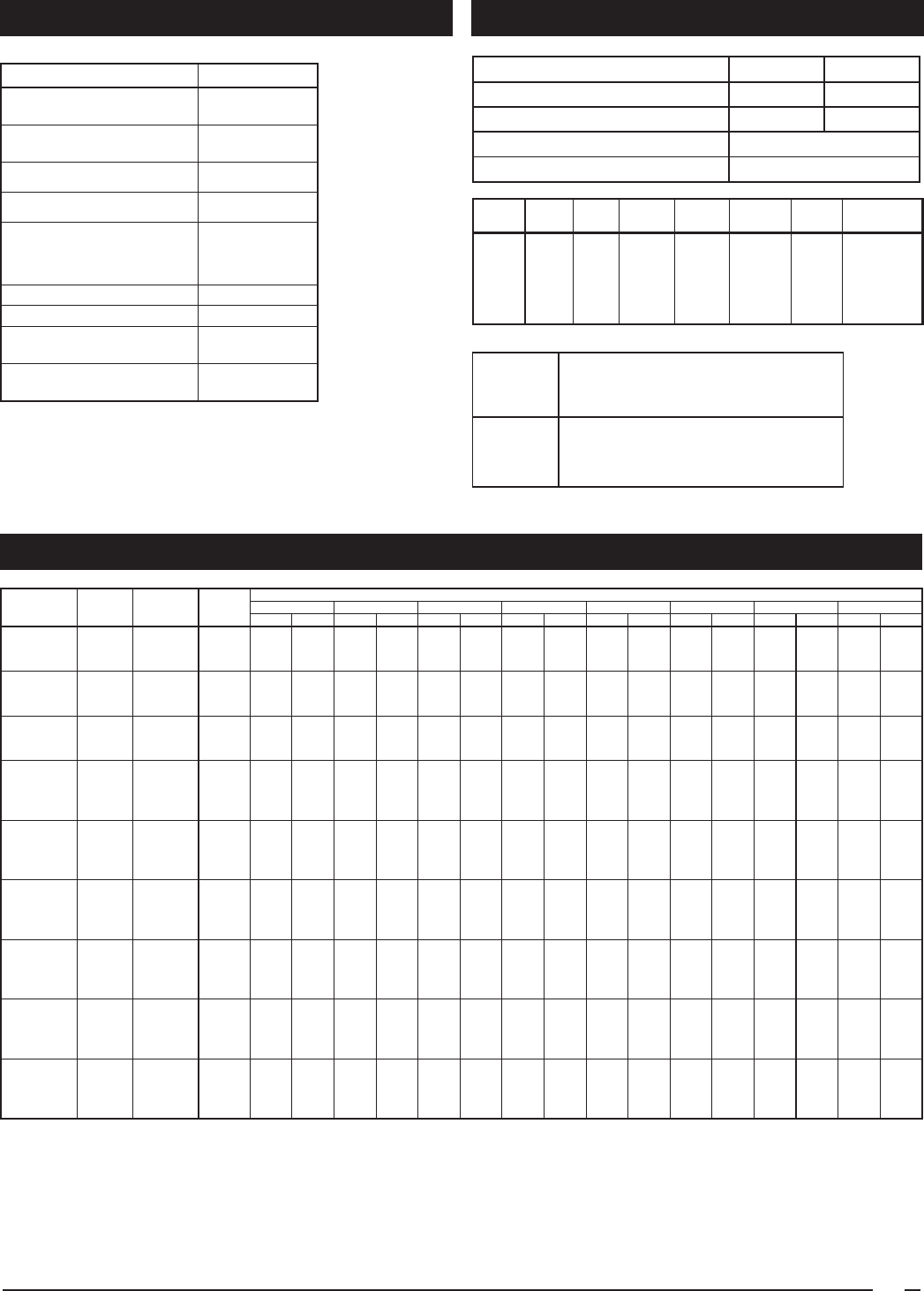
STANDARD EQUIPMENT
SPECIFICATIONS
VENTING
( ) Can be C or N
PGF1RC MODEL NUMBERS: 040( )08A 040( )12A 060( )12A 080( )12B 080( )16B 100( )16B 100( )20B 120( )16C 120( )20C
Input-Btuh (a) 40,000 40,000 60,000 80,000 80,000 100,000 100,000 120,000 120,000
Heating Capacity - Btuh 36,000 36,000 55,000 72,000 72,000 92,000 92,000 110,000 110,000
AFUE 92.1 92.1 92.1 92.1 92.1 92.1 92.1 92.1 92.1
Blower D x W 10 x 6 10 x 6 10 x 6 10 x 10 10 x 10 10 x 10 11 x 10 10 x 10 11 x 10
Motor H.P. -Speed -Type 1/5 - 3 - PSC 1/3 - 3 - PSC 1/3 - 3 - PSC 1/2 - 4 -PSC 1/2 - 4 -PSC 1/2 - 4 -PSC 3/4 - 4 -PSC 1/2 - 4 -PSC 3/4 - 4 -PSC
Motor FLA 3.0 6.0 6.0 7.9 7.9 7.9 11.1 7.9 11.1
Maximum Ext. SP - In. W.C. 0.5 0.5 0.5 0.5 0.5 0.5 0.5 0.5 0.5
Temperature Rise Range - °F 35 - 65 35 - 65 45 - 75 40 - 70 40 - 70 45 - 75 45 - 75 55 - 85 55 - 85
APPLICATION
SINGLE PIPE LENGTH (ft.)
with 1 long radius elbow*
DIRECT VENT, DUAL PIPE LENGTH (ft.)
with 1 long radius elbow on each pipe*
PVC, CPVC or ABS Outlet Outlet Inlet/Outlet Inlet/Outlet Inlet/Outlet
SCH. 40 Pipe Size 2” 3” 2” 2” 3” 2” 3” 3”
Models
040
80 150 40 40 50 50 90 90
Models
060 & 080
60 150 30 30 35 35 90 90
Models
100 & 120
30 150 15 15 25 25 90 90
7
VENT KITS ACCESSORIES
BLOWER PERFORMANCE
Kit Order Number
U.S. LP Conversion Kit
(0 to 10,000 ft.)
904090A
Canadian LP Gas Conversion Kit
(0 to 4,500 ft.)
904091A
Fossil Fuel Kit 914762
Side Return Filter Kit 541036
Bottom Return A Cabinet 903088
Filter (20/Box) B Cabinet 903089
C Cabinet 903090
Horizontal Drain Kit 903568
Internal Side Return Filter Wire 903152
Variable Speed Blower Kit
for “A” cabinets
904231
Variable Speed Blower Kit
for “B” & “C” cabinets
904075
Kit Description 2” PVC 3” PVC
Horizontal Exterior Vent Mounting Kit 902373 902375
Concentric Vent Kit 904177 904176
Neutralizer Kit (all models) 902377
Side Wall Vent Kit
904347
Furnace Cabinet Nominal Maximum Minimum Maximum on Minimum Maximum on
Input Width Electrical Operating Operating Furnace Wire Fuse or Circuit
(Btuh) (in.) Supply Voltage Voltage Amperes Gauge Breaker Amps*
40,000 14.25 115-60-1 127 103 7.8 14 15
60,000 14.25 115-60-1 127 103 7.8 14 15
80,000 19.75 115-60-1 127 103 9.7 14 15
100,000 19.75 115-60-1 127 103 9.7 14 15
120,000 22.50 115-60-1 127 103 12.9 12 20
Thermostat
Wire
Gauge
Recommended Maximum Thermostat
Wire Length
2-wire 4 or 5-wire
(heating) (cooling)
24 55 ft. 25 ft.
22 90 ft. 45 ft.
20 140 ft. 70 ft.
18 225 ft. 110 ft.
* Time-delay fuses or HACR-type circuit breakers are required.
NOTES: 1. Airfl ow rates of 1800 CFM or more require two return air connections. Data is for operation with fi lter(s).
2. Temperature rises in the table are approximate. Actual temperature rises may vary.
3. Temperature rises and airfl ows for external static pressures greater than 0.5 are for reference only.
These conditions are not recommended.
( ) Can be C or N
** Factory Set Cooling Speed
** Factory Set Heating Speed
- Not Recommended
Model Heating
External Static Pressure (Inches Water Column)
Number Input Motor Motor 0.1 0.2 0.3 0.4 0.5 0.6 0.7 0.8
*RC (Btuh) Speed HP
CFM Rise CFM Rise CFM Rise CFM Rise CFM Rise CFM Rise CFM Rise CFM Rise
High* 950 36 920 38 890 39 850 41 800 43 750 46 690 50 630 55
040( )08A 40,000 Medium** 1/5 740 47 710 49 680 51 650 53 600 58 550 63 490 - 430 -
Low 620 56 590 59 560 62 520 - 470 - 410 - 350 - 290 -
High* 1330 - 1280 - 1230 - 1170 - 1120 - 1030 - 940 37 850 41
040( )12A 40,000 Medium** 1/3 1190 - 1160 - 1110 - 1060 - 1010 - 910 38 820 42 720 48
Low 830 42 810 43 780 44 760 46 720 48 670 52 610 57 550 63
High* 1310 - 1260 - 1210 - 1160 45 1100 47 1040 50 980 53 920 56
060( )12A 60,000 Medium** 1/3 1160 45 1120 46 1080 48 1050 49 990 52 940 55 890 58 830 63
Low 800 65 780 67 760 68 740 70 710 73 680 - 650 - 620 -
High* 1775 38 1724 39 1652 40 1583 42 1505 44 1430 46 1343 49 1226 54
080( )12B 80,000 Med-High** 1/2 1417 47 1385 48 1339 50 1280 52 1224 54 1163 57 1097 61 1013 66
Med-Low 1031 65 987 67 967 69 914 73 882 75 839 - 783 - 692 -
Low 808 - 751 - 717 - 679 - 641 - 595 - 538 - 430 -
High* 1840 - 1780 - 1700 41 1630 42 1550 45 1470 47 1380 50 1290 54
080( )16B 80,000 Med-High** 1/2 1600 43 1560 44 1470 47 1400 49 1350 51 1280 54 1210 57 1150 60
Med-Low 1380 50 1350 51 1300 53 1250 55 1190 58 1120 62 1040 67 960 -
Low 1100 63 1050 66 1000 69 950 - 900 - 850 - 800 - 750 -
High* 1910 45 1860 47 1780 49 1700 51 1620 53 1520 57 1420 61 1310 66
100( )16B 100,000 Med-High** 1/2 1640 53 1620 53 1540 56 1480 58 1420 61 1340 65 1250 69 1150 75
Med-Low 1440 60 1410 61 1370 63 1320 66 1270 68 1210 72 1140 - 1060 -
Low 1230 70 1210 72 1180 73 1140 - 1090 - 1030 - 960 - 880 -
High* 2195 39 2140 40 2065 41 2000 42 1960 44 1860 46 1780 48 1695 50
100( )20B 100,000 Med-High** 3/4 1975 43 1910 44 1875 45 1845 46 1805 47 1735 50 1670 51 1590 53
Med-Low 1650 51 1615 52 1605 53 1570 54 1540 55 1485 57 1435 59 1370 62
Low 1320 64 1300 65 1280 66 1275 67 1265 67 1250 68 1210 70 1160 73
High* 1860 56 1800 58 1730 60 1650 63 1570 66 1480 70 1380 75 1270 82
120( )16C 120,000 Med-High** 1/2 1650 63 1610 65 1550 67 1480 70 1410 74 1320 79 1230 84 1120 -
Med-Low 1440 72 1410 74 1380 75 1320 79 1280 81 1220 85 1150 - 1080 -
Low 1230 84 1210 - 1180 - 1140 - 1090 - 1030 - 960 - 880 -
High* 2260 - 2200 - 2140 - 2070 - 1990 - 1910 - 1810 57 1710 61
120( )20C 120,000 Med-High** 3/4 1870 56 1840 56 1790 58 1760 59 1710 61 1660 63 1610 65 1560 67
Med-Low 1540 67 1530 68 1510 69 1470 71 1430 73 1370 76 1300 80 1220 85
Low 1360 76 1330 78 1310 79 1280 81 1250 83 1220 85 1190 - 1150 -
Before purchasing this appliance, read important energy cost and effi ciency
information available from your retailer. Specifi cations and illustrations subject
to change without notice and without incurring obligations.
Maytag is a registered trademark of the Maytag Corporation and is used under license.
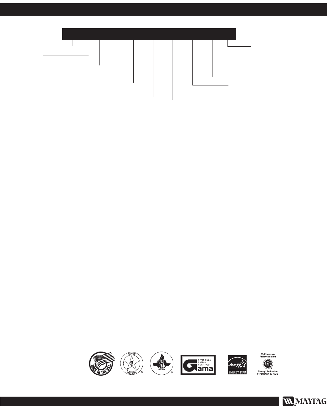
080 = 80,000
100 = 100,000
120 = 120,000
Design Series
C = Upfl ow/
Horizontal
92% AFUE
Residential
P = Premier
G = Gas
F = Full Size
Heating Input - Btuh
040 = 40,000
060 = 60,000
Approx. CFM Airfl ow
@ 0.5” WC
12 = 1200
16 = 1600
20 = 2000
276B-0207 (Replaces 276B-0107)
IDENTIFICATION CODE
C = U.S. / Canada
N = Low NOx
P G F 1 R C 120 C 20 C
Cabinet Size
A = 14-1/4
B = 19-3/4
C = 22-1/2
Printed in U.S.A. (02/07)
