®
U
P
C
W11572554A
Certied by
International Association of Plumbing and Mechanical Ocials (IAPMO) R&T
NSF/ANSI 42, 44, 61 & 372 · IPC · IRC
Reference Performance Data Sheet
WATER TREATMENT SYSTEM
OPERATION MANUAL
ST SERIES
2
TABLE OF CONTENTS
WATER TREATMENT SYSTEM SAFETY ...................................................................................................... 3
INTRODUCTION .............................................................................................................................................. 4
Main Parts .......................................................................................................................................................... 4
INSPECTION .................................................................................................................................................... 5
Valve Layout ....................................................................................................................................................... 6
Mineral Tank ....................................................................................................................................................... 6
PARTS AND FEATURES ................................................................................................................................. 6
Control Layout .................................................................................................................................................... 6
Brine Tank ........................................................................................................................................................... 6
EQUIPMENT DIMENSIONS ............................................................................................................................ 7
SYSTEM LAYOUT ............................................................................................................................................ 8
SYSTEM SPECIFICATIONS ........................................................................................................................... 9
Location Requirements..................................................................................................................................... 10
INSTALLATION INSTRUCTIONS ................................................................................................................. 10
Electrical Requirements.................................................................................................................................... 10
Mechanical Requirements .................................................................................................................................11
General Requirements ......................................................................................................................................11
EQUIPMENT INSTALLATION ....................................................................................................................... 11
Bypass Valve Operation ................................................................................................................................... 12
Brine Line and Safety Brine Valve ................................................................................................................... 13
Connections...................................................................................................................................................... 13
Safety Brine Valve Assembly ........................................................................................................................... 13
................................................................................................................ 14
Media Volume, Salt and Capacity Settings....................................................................................................... 15
Cycles and Softening Set Up............................................................................................................................ 15
SYSTEM OPERATION ................................................................................................................................... 17
Cycle Sequence ............................................................................................................................................... 19
Softener System Setup..................................................................................................................................... 20
User Display Settings ....................................................................................................................................... 25
Diagnostics ....................................................................................................................................................... 27
Valve History ..................................................................................................................................................... 29
PLACING WATER SYSTEM INTO OPERATION ........................................................................................ 31
................................................................................................................ 35
DRAWINGS AND PART NUMBERS ............................................................................................................. 35
Control Valve - Front Cover and Drive Assembly ............................................................................................. 36
Brine Tank Assembly and Parts List ................................................................................................................. 37
Mineral Tank Assembly, Valve Cover, and Parts List ........................................................................................ 38
Control Valve - Drive Cap, Piston, Regenerant Piston, and Stacker Assembly ................................................ 39
Control Valve - Injector Cap and Injector ......................................................................................................... 40
............................................................................................ 41
.................................................................................................................... 42
Water Meter, Meter Plug, and Mixing Valve...................................................................................................... 43
Bypass Valve .................................................................................................................................................... 44
Bypass Fitting Packages .................................................................................................................................. 45
BYPASS FITTING PACKAGES .................................................................................................................... 45
Bypass Fitting Packages .................................................................................................................................. 46
Bypass Fitting Packages .................................................................................................................................. 47
Bypass Fitting Packages .................................................................................................................................. 48
Bypass Fitting Packages .................................................................................................................................. 49
TROUBLESHOOTING ................................................................................................................................... 50
PERFORMANCE DATA SHEET ................................................................................................................... 56
PERFORMANCE DATA SHEET ................................................................................................................... 57
Warranty ........................................................................................................................................................... 58
Notes ................................................................................................................................................................ 59
3
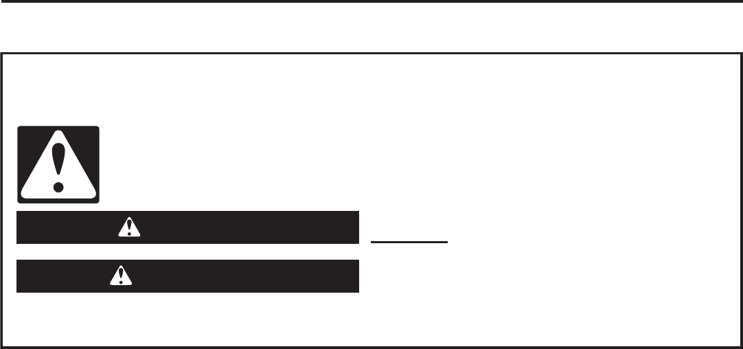
You can be killed or seriously injured if you don't
immediately follow instructions.
You can be killed or seriously injured if you don't
follow instructions.
All safety messages will tell you what the potential hazard is, tell you how to reduce the chance of injury, and
tell you what can happen if the instructions are not followed.
Your safety and the safety of others are very important.
We have provided many important safety messages in this manual and on your appliance.
Always read and obey all safety messages.
This is the safety alert symbol.
This symbol alerts you to potential hazards that can kill or hurt you and others.
All safety messages will follow the safety alert symbol and either the word
“DANGER” or “WARNING.” These words mean:
DANGER
WARNING
WATER TREATMENT SYSTEM SAFETY

4
IMPORTANT:
result in personal injury or damage to the equipment.
This purpose of this installation manual is to guide the
installer through the installation and operation process of
MAYTAG
®
This manual is a reference and not included in every
system installation situation. The technician installing this
equipment must have:
Training in the MAYTAG
®
series controllers.
proper control settings.
Basic plumbing skills.
The directional instructions “left” and “right” are
determined by looking at the front of unit.
Inspect the unit for damage or missing parts.
Contact your supplier if any discrepancies exist.
Brine Well Assembly
Water Bypass
Plumbing Connectors
Left
Right
INTRODUCTION
Outlet
Main Parts
Inlet
Figure 1: Typical Inlet/Outlet Piping and
Valves for Proper Startup and Servicing
Outlet
Treated
Water
Supply
Inlet
Untreated
Water
Supply

5
Remove system from carton:
1. Remove the box top from the system.
2.
3.
4. Remove the components from the shipping carton (bypass box, brine tube assembly, plumbing
connectors & brine tubing)
5.
To assemble the Salt Tank:
1.
One to a drain and one to the valve.
2.
3.
4.
holes in the side of the brine tank.
5.
IMPORTANT:
back quickly, the particles may enter the valve. If this happens, the valve may need to be disassembled and
cleaned.
1. Stand the tank up and in position.
2.
Figure 2
INSPECTION
inspected for damage.
If any parts are damaged or missing, contact your supplier.
IMPORTANT:
6
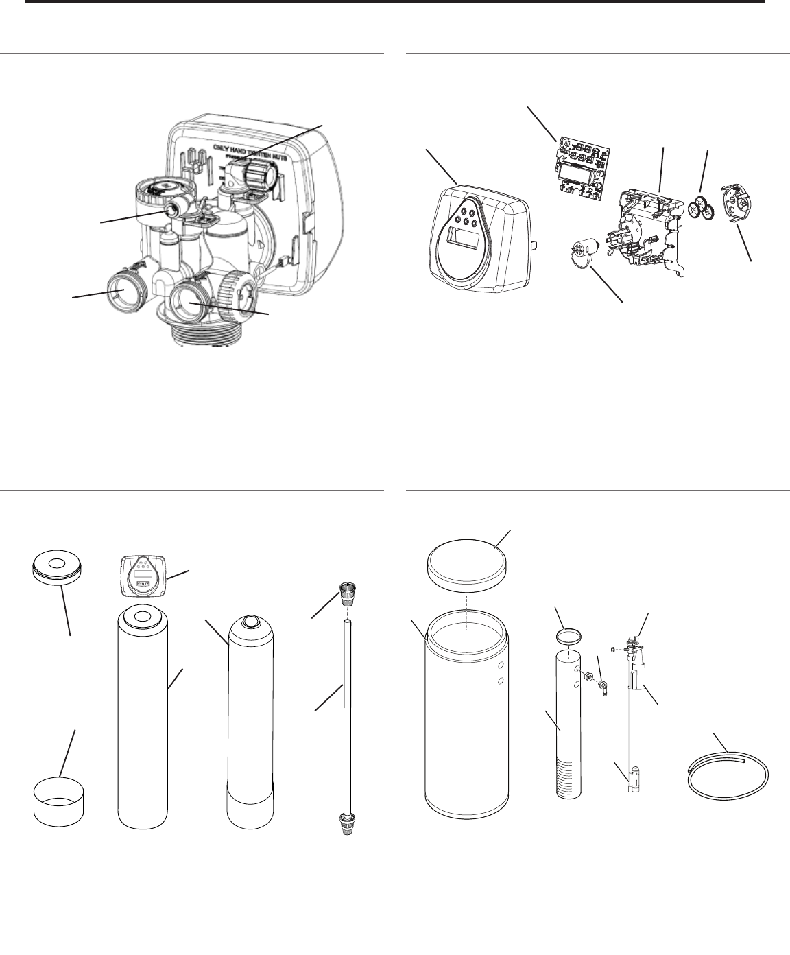
1. Tank Jacket Cover 5. Mineral Tank
2. Tank Jacket Sleeve 6. Upper Basket
3. Tank Jacket 7. Distributor Asy
4. Valve
1. Rell Flow Control Fitting 3. Untreated Water Inlet
2. Drain Fitting 4. Treated Water Outlet
1
3
1
2
3
4
5
6
1. Face Cover Assembly 4. Drive Bracket Asy
2.Circuit Board 5. Drive Gear 12x36
3. Motor 6. Drive Gear Cover
1
2
3
4
5
6
1. Cover 6. Air Check
2. Brine Tank 7. Float
3. Brine Well 8. Brine Valve Asy
4. Brine Well Cap 9. Tubing
5. Overow Fitting
7
2
4
PARTS AND FEATURES
Figure 3
Figure 4
Figure 5
Figure 6
1
4
8
2
3
7
5
6
9
Valve Layout Control Layout
Mineral Tank Brine Tank
7
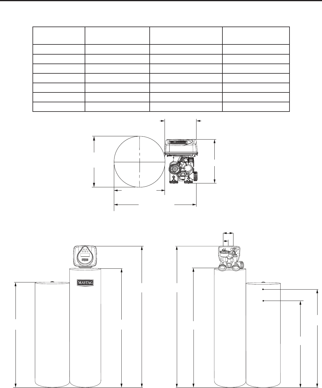
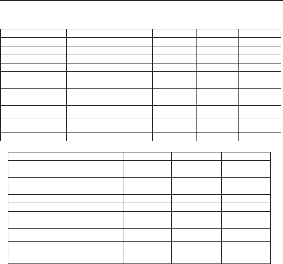
Dimensions 10 x 44” Tank
(25.4 x 111.76 cm)
1 0 x 5 4 ” T a n k
(25.4 x 137.16 cm)
13 x 54” Tank
(33.02 x 137.16 cm)
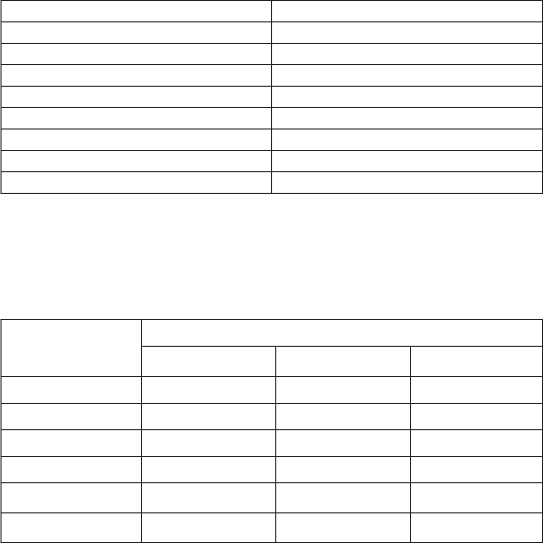
A 44.25” (112.39 cm) 54.25” (137.79 cm) 54.25” (137.79 cm)
B 52.0” (132.08 cm) 62.0” (157.48 cm) 62.0” (154.9 cm)
C 41.25” (104.77 cm) 41.25” (104.77 cm) 41.25” (104.77 cm)
D 52.0” (132.08 cm) 62.0” (157.48 cm) 62.0” (157.48 cm)
E 47.0” (119.38 cm) 57.0” (144.78 cm) 57.0” (144.78 cm)
F 32.0” (81.28 cm) 32.0” (81.28 cm) 32.0” (81.28 cm)
G 35.31” (89.68 cm) 35.31” (89.68 cm) 35.31” (89.68 cm)
EQUIPMENT DIMENSIONS
A
B
C
E
D
9.7 (24.6)
16.0 (40.6)
16.0 (40.6)
25.7 (65.2)
11.5 (29.2)
Inlet - Outlet
3 (7.6) on Center
NOTE:
7 (17.7) height for
removal of valve cover
Figure 7: Equipment Dimensions
F
G
Dimensions are given in: In (cm)
TM
8
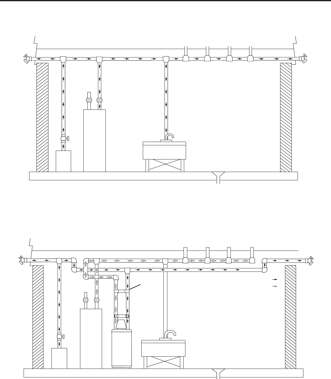
Figure 8: Standard Basement Before Installation (Cold water lines shown)
SYSTEM LAYOUT
Outside
Faucet
Kitchen
Toilet
Bath
Tub
Lavatory
Water
Heater
Hot Water
Outlet
Outside
Faucet
Laundry Tub
Pump
Or
Meter
Floor Drain
Figure 9: Treated Water Flow Diagram
Hot Water
Outlet
Outside
Faucet
Outside
Faucet
Kitchen
Toilet
Bath
Tub
Lavatory
Grounding
Strap
Untreated Water
Treated Water
Water
Rener
Laundry Tub
Water
Heater
Pump
Or
Meter
Floor Drain
Untreated WaterUntreated Water
Treated WaterTreated Water
9
Model Number 3M-ST32-XXX 3M-ST40-XXX 3M-ST48-XXX 3M-ST64-XXX 3M-ST80-XXX
Recharge Style
Mineral Tank Size 10” x 44” 10” x 54” 10” x 54” 13” x 54” 13” x 54”
Resin Volume 1.00 ft³ 1.25 ft³ 1.50 ft³ 2.00 ft³ 2.50 ft³
Recharge (Salt) Tank Size 16” x 40” 16” x 40” 16” x 40” 16” x 40” 16” x 40”
Salt Storage 338 lbs 338 lbs 338 lbs 338 lbs 338 lbs
Drain Water Rate 2.7 gpm 2.7 gpm 2.7 gpm 4.2 gpm 4.2 gpm
Service Connection Size 1” NPT 1” NPT 1” NPT 1” NPT 1” NPT
Drain Connection Size
Recharge (Brine) Connection
Size
Typical Installation Space
Requirement
28”W x 20”D x 62”H 28”W x 20”D x 72”H 28”W x 20”D x 72”H 28”W x 20”D x 72”H 28”W x 20”D x 72”H
Shipping Weight 104 lbs 121 lbs 134 lbs 174 lbs 199 lbs
Model Number 3M-STR32-XXX 3M-STR32XC-XXX 3M-STR40-XXX 3M-STR64-XXX
Recharge Style
Mineral Tank Size 10” x 44” 10” x 54” 10” x 54” 13” x 54”
Resin Volume 1.00 ft³ 1.00 ft³ 1.25 ft³ 2.00 ft³
Recharge (Salt) Tank Size 16” x 40” 16” x 40” 16” x 40” 16” x 40”
Salt Storage 338 lbs 338 lbs 338 lbs 338 lbs
Drain Water Rate 2.7 gpm 2.7 gpm 2.7 gpm 4.2 gpm
Service Connection Size 1” NPT 1” NPT 1” NPT 1” NPT
Drain Connection Size
Recharge (Brine) Connection
Size
Typical Installation Space
Requirement
28”W x 20”D x 62”H 28”W x 20”D x 72”H 28”W x 20”D x 72”H 28”W x 20”D x 72”H
Shipping Weight 116 lbs 127 lbs 133 lbs 192 lbs
SYSTEM SPECIFICATIONS

10
There are no user serviceable parts in the AC adapter,
motor, or PC board, in the event of a failure, these parts
must be replaced.
All electrical connections must be completed
according to the local codes.
the appliance.
Plug the AC adapter into an electrical outlet that is not
Indoor Location Requirements
IMPORTANT:
For indoor location of the Water Treatment System, make
Make sure to maintain the space to access the
equipment for maintenance and adding regenerant
(salt) to brine tank.
Operating ambient temperature: 34°F-120°F
(1°C-49°C).
120 psi (1.38 bar - 8.27 bar).
Maintain constant electrical supply to operate the
control.
Local drain for discharge as close as possible to the
appliance.
Must meet any local and state codes for site of
installation.
Valve is designed for minor plumbing misalignments.
Make sure that all the soldered pipes are fully cooled
before attaching plastic valve to the plumbing.
Outdoor Location Requirements
IMPORTANT:
Place the unit at the dry location only, unless listed as
use.
important measures are taken for outdoor location as
Moisture - Water projected by a nozzle against
operation of the machine.
Direct Sunlight
fade or discolor over time. The integrity of the material
INSTALLATION INSTRUCTIONS
Location Requirements
Electrical Requirements
Temperature - Extreme hot or cold temperature
unreadable but the control must continue to function.
When the temperature returns to normal operating
applications.
Insects and Dust - The controller and valve have
been designed to keep all but the smallest insects out
of the critical areas. Dust is not totally avoidable, but
cover is recommended.
11
IMPORTANT:
inlet port of the valve. When replacing an existing system,
it is possible that the inlet and outlet get exchanged or
plumbing to be installed in an opposite order. Do not
IMPORTANT:
Over time, stress can cause break of the connections.
When the bypass is used, only hand tighten the nuts.
Figure 10
NOTE:
a ground strap must be installed.
The plumbing must be self-supporting and secure
to avoid movement. A piece of metal or a ground
strap is secured to both the inlet and outlet pipes.
(See Figure 10)
IMPORTANT: Make sure that the valve and tank compo-
nents of this unit have been assembled and tightened to
can cause improper valve and tank alignment and can
WARNING
Excessive Weight Hazard
Use two or more people to move and install water
treatment system.
Failure to do so can result in back or other injury.
EQUIPMENT INSTALLATION
Mechanical Requirements
IMPORTANT:
International Plumbing Code and any local codes and
ordinances.
Do not use petroleum based lubricants, oils, or
hydrocarbon based lubricants. Use only 100% silicone
lubricants.
All plastic connections should be hand tightened.
o-ring seal is not used.
NOTE:
the plastic connections.
Soldering near the drain line must be done before
connecting the drain line to the valve. Excessive heat
Refer to the drain line requirements.
connections.
rate is greater than 7 gpm (26.5 Lpm) or the pipe
length is greater than 20 feet (6 m).
It is not recommended to use sealants on the threads.
Use thread seal tape on the threads of the 1” (2.54
threads.
Install appropriate grounding strap across the inlet and
ensure that a proper ground is maintained.
a ground strap must be installed.
General Requirements
Keep the mineral tank in the upright position. Do not
Operating ambient temperature: 34°F - 120°F (1°C -
49°C).
37.8°C).
bar - 8.27 bar).
not use ice melting salt, block salt or rock salt.
the tank.
plumbing adapters) connect to the plumbing system
to set before installing any plastic parts. Do not get
primer or solvent on o-rings, nuts, or the valve.
12
The bypass valve is typically used to isolate the control
to perform control valve repairs or maintenance. The
industry due to its versatility and state of the art design
plumbing misalignments, connections need only hand
tightening.
¹ (or
-
propylene. All seals are self-lubricating EPDM to help
avoid the valve from seizing after long periods of non-
use. Internal o-rings can easily be replaced if service
Figure 11
NORMAL
OPERATION
Figure 12
BYPASS
OPERATION
TREATED
WATER
SUPPLY
WATER
ENTERS
SUPPLY
WATER
ENTERS
SUPPLY
WATER
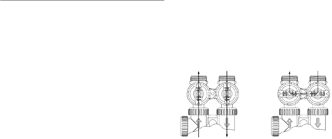
Bypass Valve Operation
is required. One internally lubricated o-ring on the rotor
creates less friction.
operate in four positions.
1. Normal Operation: The inlet and outlet handles point
control valve during normal operation and this posi-
bed during the regeneration cycle. (See Figure 11)
2. Bypass Operation: The inlet and outlet handles point
to the center of the bypass, the control valve is isolat-
system. (See Figure 12)
3. Diagnostic Mode: The inlet handle points in the
to the plumbing. (See Figure 13)
4. Shut O Mode: The inlet handle points to the center
of the bypass valve and the outlet handle points in the
building bypasses the system). (See Figure 14)
IMPORTANT: Do not use petroleum based lubricants.
installing any MAYTAG
®
brand valve. Non-silicone based
lubricants can cause plastic components to fail over time.
NOTE:
Packages”.
NOTE: The MAYTAG
®
system should be installed by
The system is located after the pressure tank (or
heater and the rest of the building.
Place the mineral tank and brine tank in position.
Use the bypass and plumbing adapters and connect
the valve to the building plumbing. Make sure that the
and outlet of the plumbing. “Water Line Connection”.
Connect the brine line. See "Brine Line Connection to
Valve”.
Connection".
"Installation Instructions", “Equipment Installation”,
“System Operation” and “Placing Water System into
Operation”.

13
Figure 13
DIAGNOSTIC
MODE
Figure 14
SHUT OFF
MODE
NO WATER
SUPPLY
WATER
ENTERS
SUPPLY
WATER
SUPPLY
SHUT OFF
FROM THE
VALVE
Figure 16
Brine Line Insertion
Figure 15
Brine Line Connection to Valve
2
1
3
The brine line must be connected from the control valve
to the safety brine valve assembly in the brine tank. Be
sure that the brine line tube is secure and free from air
leaks. Even a small leak may cause the brine line tube to
the brine tank. This may also introduce air into the valve
1. Trim tubing to length. Be sure tubing is free of debris,
past the quad seal.
2. -
ing goes past the quad seal and properly bottoms in
and hold and seal it in place.
3. To remove the tubing, push the collet around the
tubing in and at the same time pull the tubing out.
Figure 17
Safety Brine Valve Assembly
1. 474 Air Check Assy. with ½" (1.27 cm) riser pipe.
2. 474 Safety Brine Valve with ⅜" (0.95 cm) elbow.
3. 474 Float Assy.
Figure 18
Safety Brine Valve
1. Rell Flow (regenerant) Control Fitting
2. Drain Fitting
3. Locking Clip (2) Required
Brine Line and Safety Brine Valve
Connections
Safety Brine Valve Assembly
2
3
1
14
2
1
Overow Fitting
Drain Tubing
Secure hose in place
Air Gap
Drain
Figure 19
Secure Drain Line
NOTE: Standard commercial practices are expressed
-
ing a system.
1. The unit should be above and not more than 40 feet
cm) drain line or the optional nut and poly tube insert
poly tube drain line connection. Use thread seal tape
or CPVC pipe to the drain line connection of the con-
180 degrees so the drain lince can be orientated to
the nearest drain.
2.
or if the unit is located more than 40 feet (12.2 m)
from drain, use ¾" (1.9 cm) tubing, PVC or CPVC
(1.9 cm) tubing, PVC or CPVC pipe to the drain con-
nection of the control valve.
3. The drain line may be elevated up to 6 feet (1.8 m)
providing the run does not exceed 40 feet (12.2 m)
psi (2.76 bar). Elevation can increase by 2 feet (61
pressure at the drain connector.
4. Where the drain line is elevated but empties into a
(17.7 cm) loop at the far end of the line o that the bot-
the hose in place at the drain point. Also provide an
the hose and the drain point.
5.
line, a sink-type trap must be used.
6. Secure the end of the drain line to avoid it from mov-
ing.
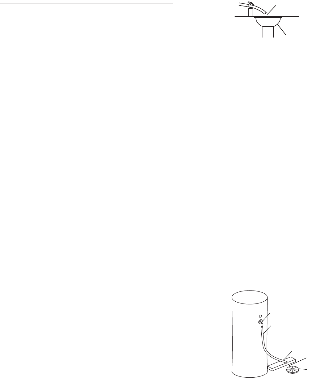
In the event of a malfunction, the brine (regenerant) tank
-
line tubing hole on the side of the brine tank.
(See Figure 20)
Drain Tubing sold separately in 100 ft rolls
(Part No. 3PET58100B).
NOTE:
instructions.
Figure 20
Brine Tank with Overow Fitting
Overow Line Connection
Drain Line Connection
1. Overow Fitting 4. Air Gag
2. Drain Tubing 5. Drain
3. Secure hose in place
1
2
3
4
5
1. Air Gap
2. Drain
1
2
Drain Line and Overow Connection
Drain Line Connection

15
1. Overow Fitting 4. Air Gag
2. Drain Tubing 5. Drain
3. Secure hose in place
Table
each resin amount.
E = High Eciency salt, approximately 6 lbs.
per cu. ft. of media
S = Standard salt, approximately 9 lbs.
per cu. ft. of media
Q = Quality salt, approximately 15 lbs.
per cu. ft. of media
Media
Volume
(ft) ³
Salt
Setting
Total Salt
Amount Per
Regenera-
tion (lbs)
Estimated
Capacity
(kg)
E 3 10,000
0.5 S 4.5 13,000
Q 7.5 15,000
E 4.5 15,000
0.75 S 7 19,000
Q 11 23,000
E 6 20,000
1.0 S 9 25,000
Q 15 30,000
E 7.5 25,000
1.25 S 11 34,000
Q 19 38,000
E 9 30,000
1.5 S 13.5 38,000
Q 22.5 45,000
E 12 40,000
2.0 S 18 50,000
Q 30 60,000
E 15 50,000
2.5 S 22.5 67,000
Q 37 75,000
E 18 60,000
3.0 S 27 75,000
Q 45 90,000
Table 1
Water Treatment System Set Up: Softening
Media Volume, Salt Amounts and Estimated Capacity
Media Volume, Salt and Capacity Settings Cycles and Softening Set Up
The Maytag® series
treatment professional has the option of having the re-
When setting up the system refer to Table 1 to select the
volume of media, the total salt amount per regeneration
(lbs) and the estimated capacity for the system.
NOTE: The regeneration cycle times are fully adjustable.
Refer to Table 3.
16
Table 3
Regeneration Cycle Times in Units
Table 2
System Cycles
1st Cycle: Fill Rinse (0:00:15 SEC)
Dissolve Brine
Rinse (0:00:15 SEC)
3rd Cycle: Rinse
4th Cycle: Rinse 5th Cycle: Service
Fill (0:00:05 SEC)
5th Cycle: Service
Cycle
Range
Softening
Filtering-Regenerant
oFF, 1 - 120 (Minutes) oFF, 1 - 120 (Minutes) oFF, 1 - 120 (Minutes)
oFF, 1 - 180 (Minutes) oFF, 1 - 180 (Minutes)
Rinse oFF, 1 - 120 (Minutes) oFF, 1 - 120 (Minutes) oFF, 1 - 120 (Minutes)
Fill (Regenerant) oFF, 0.1 - 200.0 (lbs) oFF, 0.05 - 20.00 (gals)
Softening 1 - 480 (Minutes)
Filtering 1 - 480 (Minutes) 1 - 480 (Minutes)
17
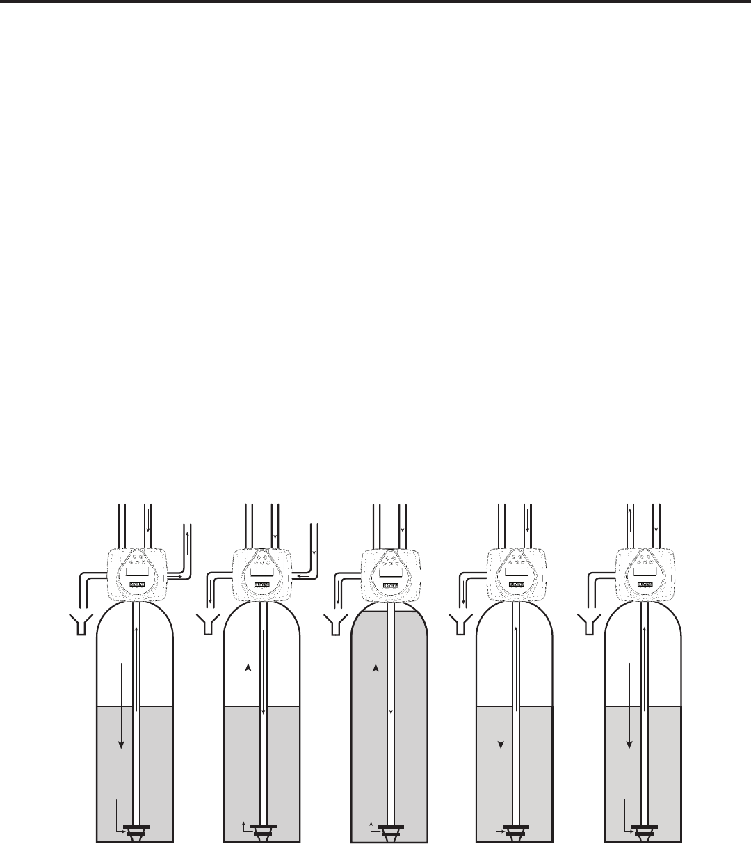
Fill/Dissolve Water
Regenerate (Upow)
drain. The hardness ions are displaced by sodium ions and are sent to the drain. The resin is regenerated
Backwash (Upow)
Rinse (Downow)
the drain. Any remaining brine residual is rinsed from the resin bed.
Service (Downow)
as it passes through the resin bead.
Figure 21
Cycle Water Flows
To
Regenerant
Tank
Fill/Dissolve
From
Regenerant
Tank
Regenerate
Backwash
ServiceRinse
SYSTEM OPERATION
18
General Programming Instructions
These procedures are:
Once the Cycle Sequence has been set, the other procedures can be accessed in any order. Details on each of the
-
and CLOCK in sequence.
incorporated.
To quickly exit Softener Setup, Diagnostics or Valve History press CLOCK. Any changes made prior to the exit are
incorporated.
the preset regeneration procedure. It is possible to do a double regeneration if the control valve is set to “NORMAL” or
“NORMAL + “On 0” in Softener System Setup or Filter System Setup. To do a double regeneration:
2. Press and hold the “REGEN” button for three seconds until the valve regeneration initiates.
-
generation time.
are being used, and that the injector plug(s) are in the correct location. Refer Figure 29 & Figure 30.
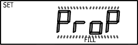
Proportional Brining
brining.
Press NEXT to go to the next step. Press REGEN to return to the previous step.
Cycle Sequence Diagnostics
Softener System Setup Valve History
User Display Settings
19
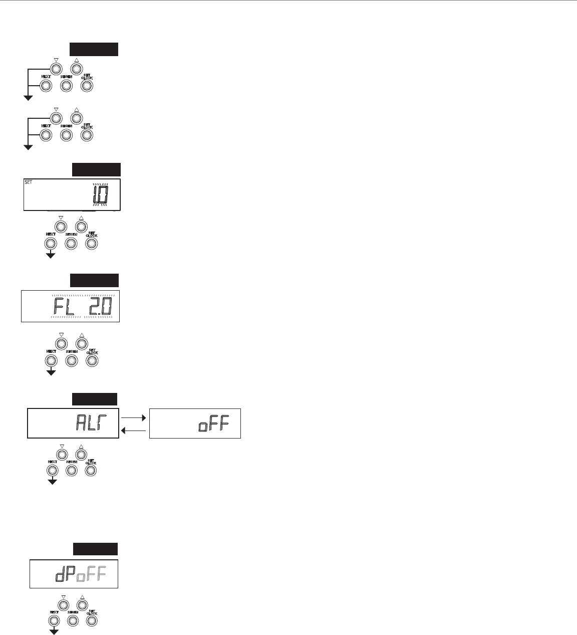
STEP 1C
Step 1C
Step 2C
(SET TO 1.0)
Press NEXT to go to next Step. Press REGEN to return to exit Cycle Sequence.
STEP 2C
Step 3C
(Variable Meter Calibration.) Variable meter pulses of 0.1-150.0 PPG can be selected.
STEP 3C
Step 4C –
• the Control Valve to act as an alternator; or
• the Control Valve to have a Separate Source during the
regeneration cycle; or
(SET TO oFF)
Press NEXT to go to Step 5C. Press REGEN to return to exit
Cycle Sequence.
STEP 4C
SET
STEP 5C
SET
SET
SET
Step 5C – dp Select OFF using the
(SET TO oFF)
Press NEXT to go to Step 6C. Press REGEN to return to previous step.
SET
Cycle Sequence

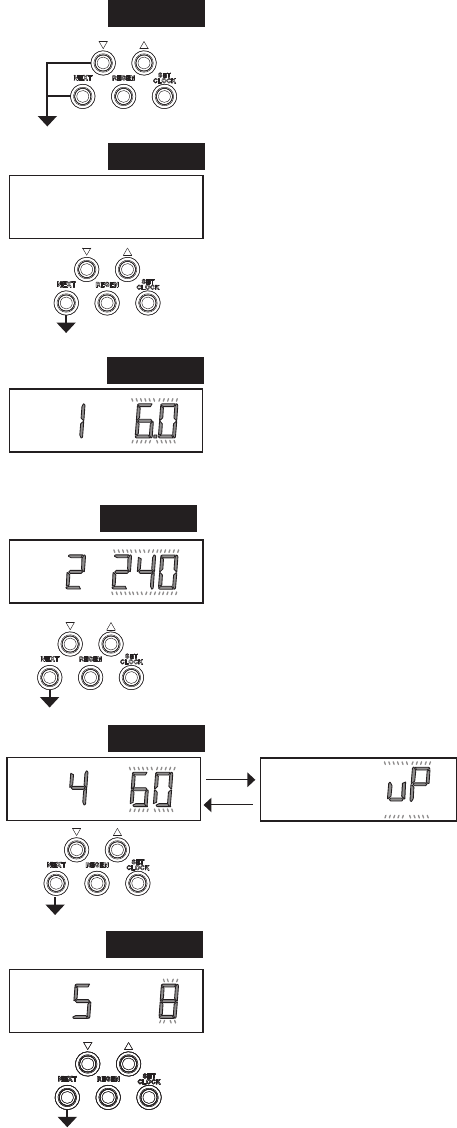
20
Step 6C
(SET TO PrE)
Press NEXT to go to Step 7C. Press REGEN to return to previous step.
Step 7C
(SET TO uP)
regenerant piston, and stack are being used, and that the injector or injector plug(s) are
Press NEXT to Return to NORMAL MODE. Press REGEN to return to previous step.
STEP 6C
STEP 7C
RETURN TO
NORMAL MODE
SET
FILL
REGEN
SET
REGEN
BRINE
.
Step 6C Step 7C Cycle Order
Post dn
Pre dn
Post UP
Pre UP
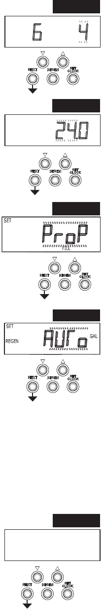
NOTE:
the Grains Capacity display (Step 8S).
Softener System Setup
21
STEP 1S
Step 1S – Press NEXT and simultaneously for 3 seconds and release. If screen in Step
2S does not appear in 5 seconds the lock on the valve is activated. To unlock press ,
NEXT,
and release.
STEP 2S
Step 2S.
(SET TO SOFTENING)
Press NEXT to go to Step 3S. Press REGEN to exit Softener System Setup.
STEP 4S
Step 3S or .
Refer to Table 1 for salt setting.
(SET LBS OF SALT)
Press NEXT to go to Step 4S. Press REGEN to exit Softener System Setup.
Step 4S
using or .
time.
(FACTORY SET TO 240 MIN)
Press NEXT to go to Step 5S. Press REGEN to exit Softener System Setup.
STEP 3S
Step 5S
using or .
and brine direction (dn or uP).
(SET TO UP)
Press NEXT to go to Step 6S. Press REGEN to return to
previous step.
STEP 5S
SET
LBS
FILL
SET
SOFTENING
SET
BRINE
MIN
SOFTENING
SET
MIN
BRINE
SET
REGEN
BRINE
Step 6S
or .
Press NEXT to go to Step 7S. Press REGEN to return to previous step.
STEP 6SSTEP 6S
SET
MIN
BACKWASH
22
Step 7S
Press NEXT to go to Step 8S. Press REGEN to return to previous step.
Step 8S
The capacity and hardness levels entered are used to automatically calculate reserve capacity
Refer to Table 1 for capacity setting.
(SET CAPACITY)
Press NEXT to go to Step 9S. Press REGEN to return to previous step.
Step 9S
(SET TO ProP)
Press NEXT to go to Step 10S. Press REGEN to exit Softener System Setup.
Step 10S
estimated;
Refer to Programming: Installer Settings Step 3I; or
Step 2I.
appear.
Refer to Setting Options Table
(SET TO AUTO)
Press NEXT to go to Step 11S. Press REGEN to return to previous step.
Step 11S If value is set to:
or
Refer to Setting Options Table for more detail.
“on 0” is the default if Step 2C is set to 1.0T, and “NORMAL + on 0” is not available.
(SET TO NORMAL)
Press NEXT to go to Step 12S. Press REGEN to return to previous step.
STEP 7S
STEP 8S
STEP 9S
STEP 10S
STEP 11S
SET
MIN
RINSE
SET
CAPACITY
x1000
SET TIME
REGEN
NORMAL

23
Step 15S: Set the Service Call Indicator by using or . Range
is in ¼ of a year increments from 0.25 to 9.75 years. Selecting
Press NEXT to go to Step 16S. Press REGEN to return to
previous step.
RETURN TO
NORMAL MODE
STEP 15S
Step 12S – Set Relay operation using or . The choices are:
• Set Time: After the start of a regeneration the amount of time that
should pass prior to activating the relay. The start of regeneration is
• Set Softening Gal: Relay activates after a set volume has been used
and the set time period has expired.
• Set Softening Regen Gal: Relay activates after a set volume has been
• Set HoLd Gal: Relay closes every set number of gallons and releases
is pressed.
(SET TO OFF)
Press NEXT to go to Step 13S. Press REGEN to return to previous
step.
STEP 12S
Step 13S: Set Relay Actuation Time or Gallons using or The choices are:
• Relay Actuation Time: After the start of a regeneration the amount of time that should pass
• Relay Actuation Gallons: Relay activates after a set number of gallons have passed.
Ranges from 1 to 100 gallons.
• Relay HoLd: Relay closes every set number of gallons. Ranges from 1,000 to 99,000,000
gallons.
Press NEXT to go to Step 14S. Press REGEN to return to previous step.
STEP 13S
Step 14S: Set Relay Deactivate Time using or .
Ranges from 1 second to 500 minutes.
• Does not display for HoLd Gal selection.
Press NEXT to go to Step 15S. Press REGEN to return to previous step.
STEP 14S
Step 16S: Displays time remaining before a service call is requested. To reset the time
NOTE:
reminder screen is displayed.
STEP 16S
SET
SET

24
1
SETTING OPTIONS TABLE
1
System Type
Regeneration
Option
Regeneration
Type
Day
Override
Softening Auto Normal 1-28 days
Regeneration occurs at the next
Softening Auto Normal OFF
Regeneration occurs at the next
Softening or
Filtering
20 - 1,500,000
Gallons
Normal 1-28 days
Regeneration occurs at the next
Softening or
Filtering
20 - 1,500,000
Gallons
Normal OFF
Regeneration occurs at the next
reaches 0.
Softening or
Filtering
OFF Normal 1-28 days
Time Clock operation.
Regeneration occurs at the next
days is reached.
Softening
Auto or
20 - 1,500,000
Gallons
On 0 1-28 days
Softening or
Filtering
20 - 1,500,000
Gallons
On 0 OFF
volume capacity reaches 0.
Softening Auto Normal + On 0 1-28 days
Regeneration occurs at the next
regeneration occurs after 10 minutes of no
0.
Softening or
Filtering
20 - 1,500,000
Gallons
Normal + On 0 1-28 days
Regeneration occurs at the next
days is reached or regeneration occurs after
capacity reaches 0.
Softening Auto Normal + On 0 OFF
Regeneration occurs at the next
regeneration occurs after 10 minutes of no
0.
25
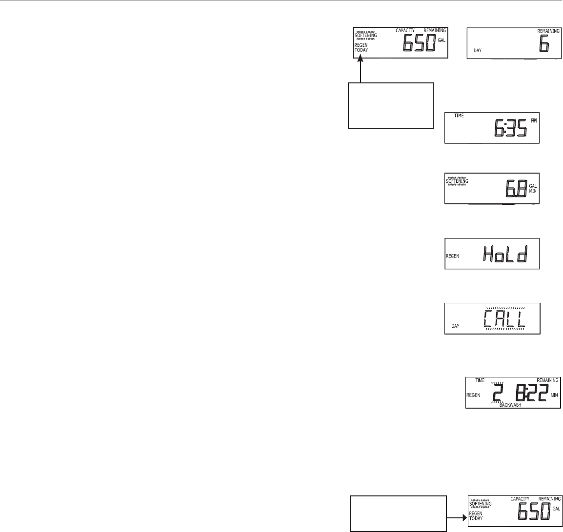
General Operation
Days remaining is the number of days left before the system goes
be treated before the system goes through a regeneration cycle.
closed.
display.
the system).
or
REGEN TODAY
regeneration is
expected “Tonight.”
Flash if a regeneration
is expected “Tonight.”
Regeneration Mode
regeneration process and the time remaining for that step to be completed. The system runs through the steps
Manual Regeneration
the system calls for it, usually referred to as manual regeneration. There
laundry day.
“NORMAL
regenerate immediately. The request cannot be canceled.
NOTE:
regenerating.
User Display Settings
26
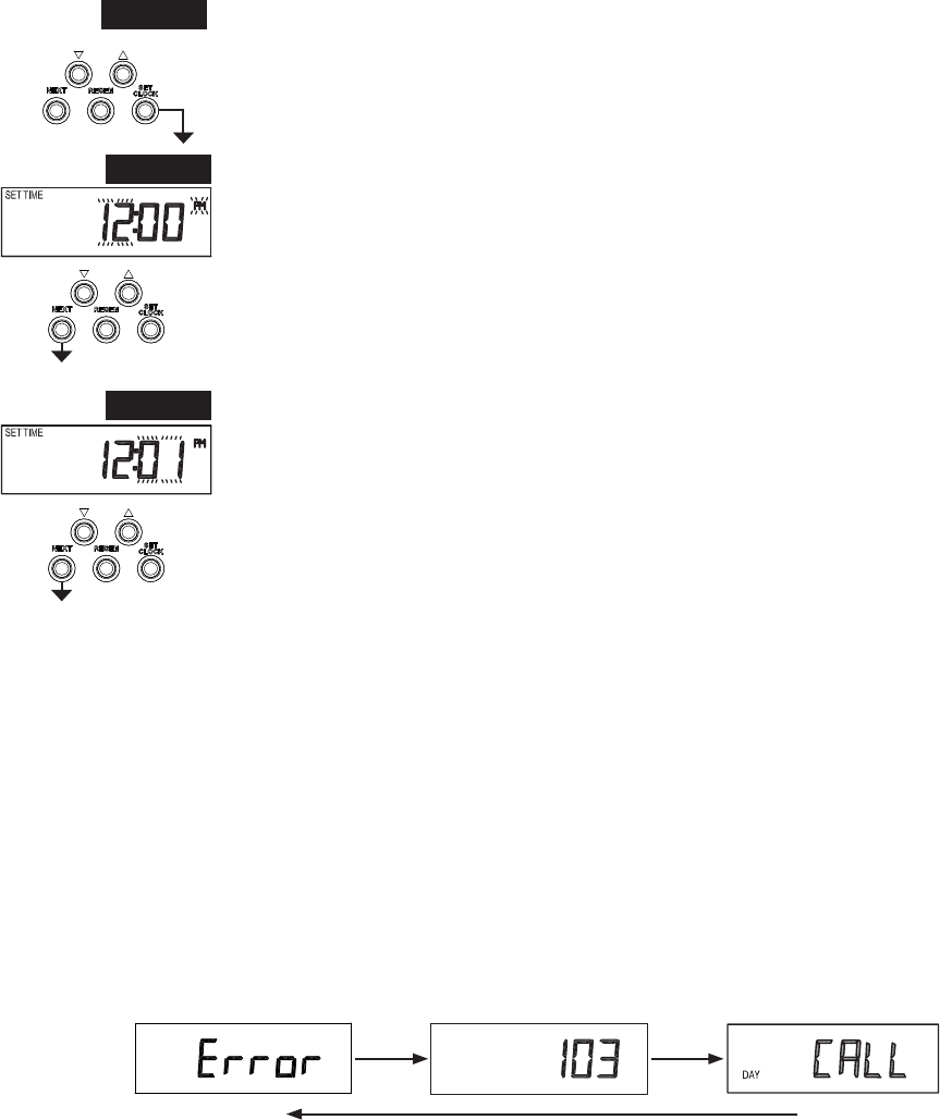
Set Time of Day
The user can also set the time of day. Time of day should only need to be set if the battery has been depleted because
be replaced.
STEP 1U
STEP 2U
STEP 3U
RETURN TO
NORMAL MODE
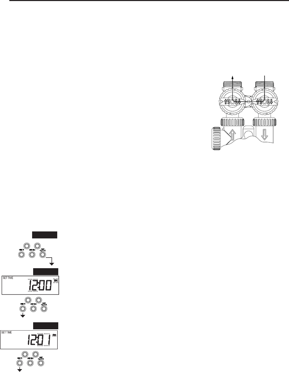
STEP 1U – Press SET CLOCK.
STEP 2U - Current Time (hour): Set the hour of the day using or
after 12. Press NEXT to go to Step 3U.
STEP 3U - Current Time (minutes): Set the minutes of the day using or . Press
NEXT to exit Set Time of Day. Press REGEN to return to previous step.
Power Loss
Error Message
27
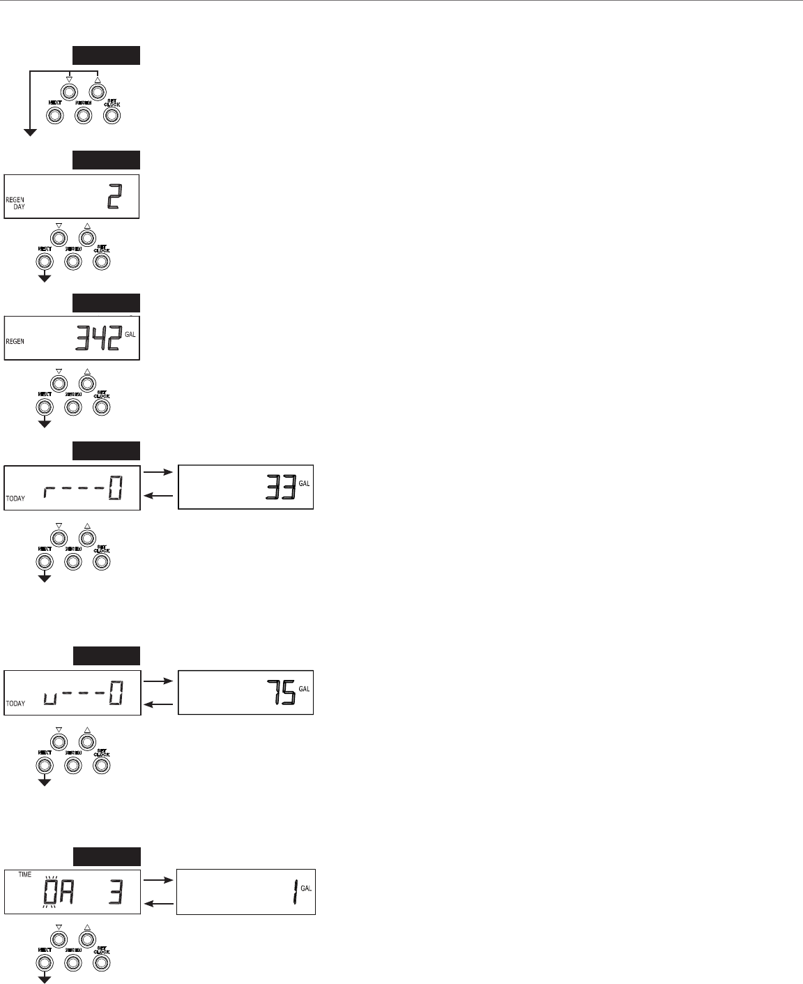
STEP 1D
NEXT,
CLOCK in sequence, then
STEP 1D
STEP 2D
STEP 2D
regeneration occurred. Press NEXT to go to Step 3D. Press REGEN to exit Diagnostics.
STEP 3D
STEP 3D
installed. Press NEXT to go to Step 4D. Press REGEN to return to previous step.
STEP 4D
STEP 4D – Volume, reserve capacity used for last 7 days: If the valve
is set up as a softener, a meter is installed and Set Volume Capacity
time to go to Step 5D. Press REGEN to return to previous step.
STEP 5D
STEP 5D
6D. Press REGEN to return to previous step.
STEP 6D
Press NEXT to go to Step 7D. Press REGEN to return to previous step.
STEP 6D
Diagnostics

28
STEP 8D
9D. Press REGEN to return to previous step.
STEP 8D
STEP 9D
NEXT to go to Step 10D. Press REGEN to return to previous step.
STEP 9D
STEP 10D
regenerations that have occurred since startup. Press NEXT to go to Step 11D. Press REGEN
to return to previous step.
STEP 10D
STEP 7D
meter is not installed. Press NEXT to go to Step 8D. Press REGEN to return to previous step.
STEP 7D
STEP 11D – MAV Drive History in the direction of extended piston rod
move is displayed as “1710”. Press NEXT at any time to go to Step
12D. Press REGEN to return to previous step.
Press and hold
11D to reset the MAV drive history in both the retracted
drive history data for retracted and extended rod position
press and hold REGEN and
NEXT to advance display to the old MAV drive history.
STEP 11D
29
Press and
User Display.
RETURN TO
NORMAL MODE
STEP 12D
STEP 12D – MAV Drive History in the direction of retracted piston
12D to reset the MAV drive history in both the extended and retracted piston rod position.
Press NEXT at any time exit Diagnostics. Press REGEN to return to previous step.
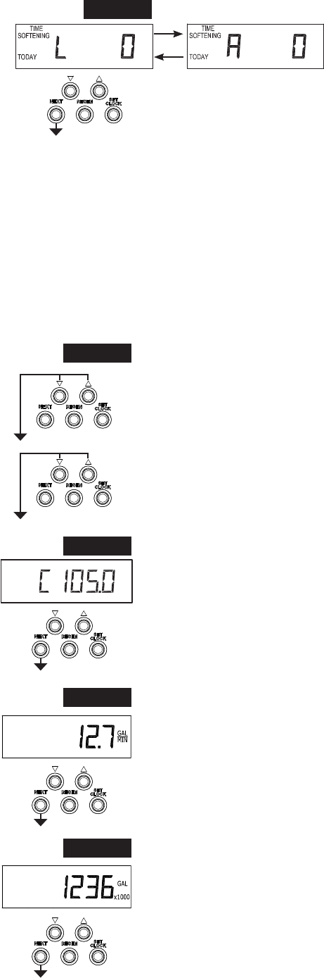
STEP 1VH
simultaneously and release.
STEP 1VH
STEP 2VH
2
Press NEXT to go to Step 3VH. Press REGEN to exit Valve History.
STEP 3VH
meter is not installed. Press NEXT to go to Step 4VH. Press REGEN to return to previous
step.
STEP 4VH
to Step 5VH. Press REGEN to return to previous step.
STEP 2VH
STEP 3VH
STEP 4VH
Valve History
30
STEP 5VH
Press NEXT to go to Step 6VH. Press REGEN to return to previous step.
STEP 5VH
2
Values in steps 2VH through 7VH cannot be reset.
RETURN TO
NORMAL MODE
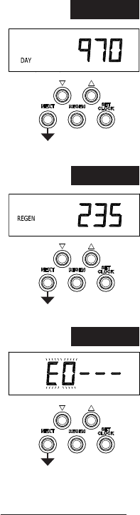
STEP 6VH
number of regenerations that have occurred since startup. Press NEXT to go to Step 7VH.
Press REGEN to return to previous step.
STEP 7VH
Valve History. Press REGEN to return to previous step.
STEP 6VH
STEP 7VH
31
Open the inlet ball valve.
Close the inlet boiler drain.
Close the outlet ball valve.
Figure 22
to the right
Open the outlet boiler drain on the outlet side of the system.
a bucket or garden hose to purge color, cement, sealants or solder
residue.
Once the lines are clear close the outlet boiler drain.
position proceed to the next section.
1. Flush water lines
NOTE:
Figure 22
2. Plug in, initialize, and set time on the water system control
STEP 1U – Press CLOCK.
STEP 1U
STEP 2U
STEP 3U
RETURN TO
NORMAL MODE
STEP 2U - Current Time (hour): Set the hour of the day using ▼or ▲
after 12. Press NEXT to go to Step 3U.
STEP 3U - Current Time (minutes): Set the minutes of the day using or . Press
NEXT to exit Set Time of Day. Press REGEN to return to previous step.
PLACING WATER SYSTEM INTO OPERATION
index the piston to the service cycle..
SUPPLY
WATER
ENTERS
SUPPLY
WATER
32
3. Fill mineral tank, purge air, backwash and rinse to ush lines
Press and hold REGEN button more than 3 seconds until the motor starts. Wait until the motor stops and display
Press and release the REGEN button each time the motor stops to advance through each cycle until you reach the
“BACKWASH” cycle. Once in the “BACKWASH” cycle.
IMPORTANT:
proceed to next step.
back in. Then press and release the REGEN button, once the motor stops, press and release the REGEN button
completely clear.
Continue to next section.
4. Brine cycle check & initial brine tank ll
NOTE:
Press and hold the REGEN button more than 3 seconds until the motor starts. Wait until the motor stops and
display
Maytag
®
series codirect
When Pre Fill is selected in set up press and release the REGEN button to advance to the next cycle. Each time
the motor stops, press and release the REGEN button to advance through each cycle until you reach the “BRINE”
cycle
Continue to next section.

33
5. Brine cycle check & initial brine draw
With the controller in the “BRINE” cycle, check to see that
troubleshooting section.
REGEN button to advance to the next cycle. Each time the motor stops, press
and release the REGEN button again until you reach the “SERVICE” position.
(Refer to Figure 23)
Check all plumbing for leaks.
Place salt (regenerant) in the brine tank. Replace cover on brine tank securely.
Continue to next section.
SUPPLY
WATER
ENTERS
“TREATED”
WATER
EXITS
Figure 23
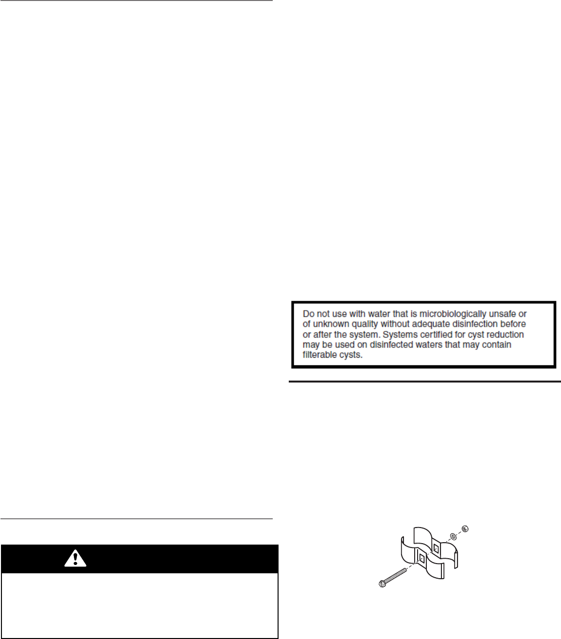
6. To Sanitize and Disinfect the System (last step after placing the system into operation)
Depending upon the conditions of use, the style of Water Treatment Sytem, the type of ion exchanger, and the
Sodium or Calcium Hypochlorite
5.25% Sodium Hypochlorite.
These solutions are available under trade names such as Clorox*. If stronger solutions are used, such as those sold
for commercial laundries, adjust the dosage accordingly.
• Dosage
• Regenerant tank conditioners
*Clorox is a trademark of the Clorox Company.
Calcium Hypochlorite
Calcium hypochlorite, 70% available chlorine, is available in several forms including tablets and granules. These solid
• Dosage
• Regenerant tank

34
7. Programming: Installer Settings
time of day is programmed on page 26.
STEP 2I
STEP 5I
STEP 6I
STEP 3I
STEP 1I - Press NEXT and ▲ simultaneously for 3 seconds.
STEP 2I – Hardness: Set the amount of hardness in grains of hardness as calcium carbonate
per gallon using ▼ or ▲
Note: The grains per gallon can be increased if soluble iron needs to be reduced. This display
Capacity in Softener System Setup.
Press NEXT to go to step 3I. Press REGEN to exit Installer Display Settings.
STEP 3I – Day Override: When volume capacity is set to “oFF”, sets the number of days
AUTO or to a number, sets the
maximum
used to call for a regeneration. Set Day Override using ▼ or ▲:
• “oFF”.
Refer to Setting Options Table for more detail on setup.
Press NEXT to go to step 4I. Press REGEN to return to previous step.
STEP 4I – Backlight Operation: Set the normal activity of the backlight. Set to ON, the backlight
Press NEXT to go to Step 5I. Press REGEN to return to previous step.
STEP 5I – Next Regeneration Time (hour): Set the hour of day for regeneration using ▼ or ▲.
selected in Set Regeneration Time Option in Softener System Setup or Filter System Setup.
Press NEXT to go to step 6I. Press REGEN to return to previous step.
STEP 6I – Next Regeneration Time (minutes): Set the minutes of day for regeneration using
▼ or ▲
Softener System Setup or Filter System Setup.
Press NEXT to exit Installer Display Settings. Press REGEN to return to previous step.
STEP 4I
STEP 1I
RETURN TO
NORMAL MODE
The MAYTAG
®
35
4
3
1
2
5
FRONT
BACK
Figure 24
Figure 25
5
2
6
4
3
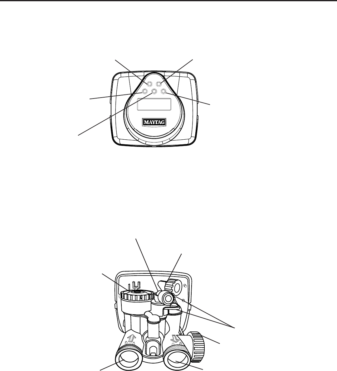
1. Regen Button 4. Up Button
2. Next Button 5. Set Clock
3. Down Button
7
1
1. Inlet 5. Locking Clip (2) Required
2. Injector Cap 6. Meter Assembly
3. Brine Fitting w/Nut 7. Outlet
4. 3/4 inch Drain Line Flow Control Assembly
DRAWINGS AND PART NUMBERS
Control Valve - Front and Back View

36
Front Cover and Drive Assembly
Drawing No. Mfg. Part No. Description Quantity
1 V4378 Front Cover Assembly 1
2 V3107-01 Motor 1
3 V3002-A Drive Bracket Asy 1
4 V4404LD-BOARD LD PC Board 1
5 V3110 Drive Reducing Gear 12x36 3
6 V3109 Drive Gear Cover 1
7 V3106-01 Drive Bracket & Spring Clip 1
V3186-06 1
V3946 Wide Backplate 1
PC Board Relay
Terminal Block
1
5
6
7
3
2
4
1
2
3
4
5
6
7
Battery replacement is
3 volt lithium coin cell
type 2032.
Correct
Battery
Orientation
When replacing the battery, align
Figure 26
There are no user serviceable parts are on the PC board, the motor or the AC adapter.
U.S. International
Supply Voltage 100-120 VAC 100-240 VAC
Supply Frequency
Output Voltage 15 VDC 15 VDC
Output Current 500 mA 500 mA
Relay Driver Output Type – Single Solid-State 12VDC
Relay Driver Output Capacity - 12VDC @100mA.
NOTE: Check for proper mounting dimensions on valve back
plate prior to mounting an external relay under control cover.
PC Board Relay
Terminal Block
Relay
RLY 1 Coil -
COM Coil +
Control Valve - Front Cover and Drive Assembly
37
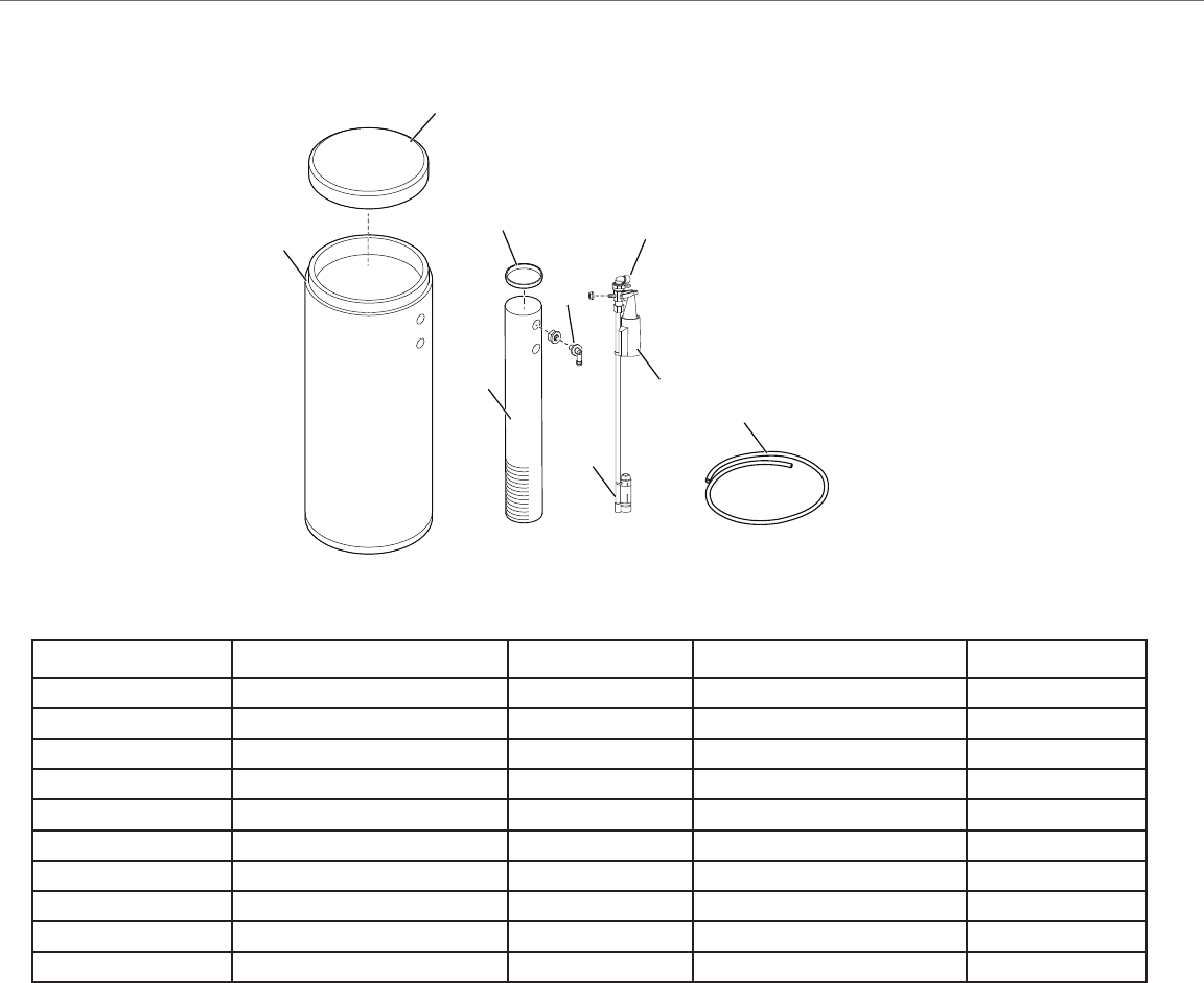
Drawing No. Part No. Mfg. Part No. Description Quantity
1 3BTCVR16GRAYNL-M 1
***2 3BTASY1640MOBILGREY 1
3 3BW436SL H1030-36S 1
4 3BWCAP4 H7016 Brine Well Cap 2
5 3OF2PC H1018 1
6 3BVACPU474 H4500-48 Air Check Assembly 1
7 3BVFLOAT4749 H4640-9.5 1
8 H4600 1
**9 3PET38BLK100 2T20-0604BK Tubing 1
* 3LLB-M-BT_2.85X11.85 309060 Brine Tank Cover Label 1
need to be ordered separately
Brine Tank Assembly and Parts List
1
4
8
2
3
7
5
6
9
Figure 27
38
3
5
2
1
8
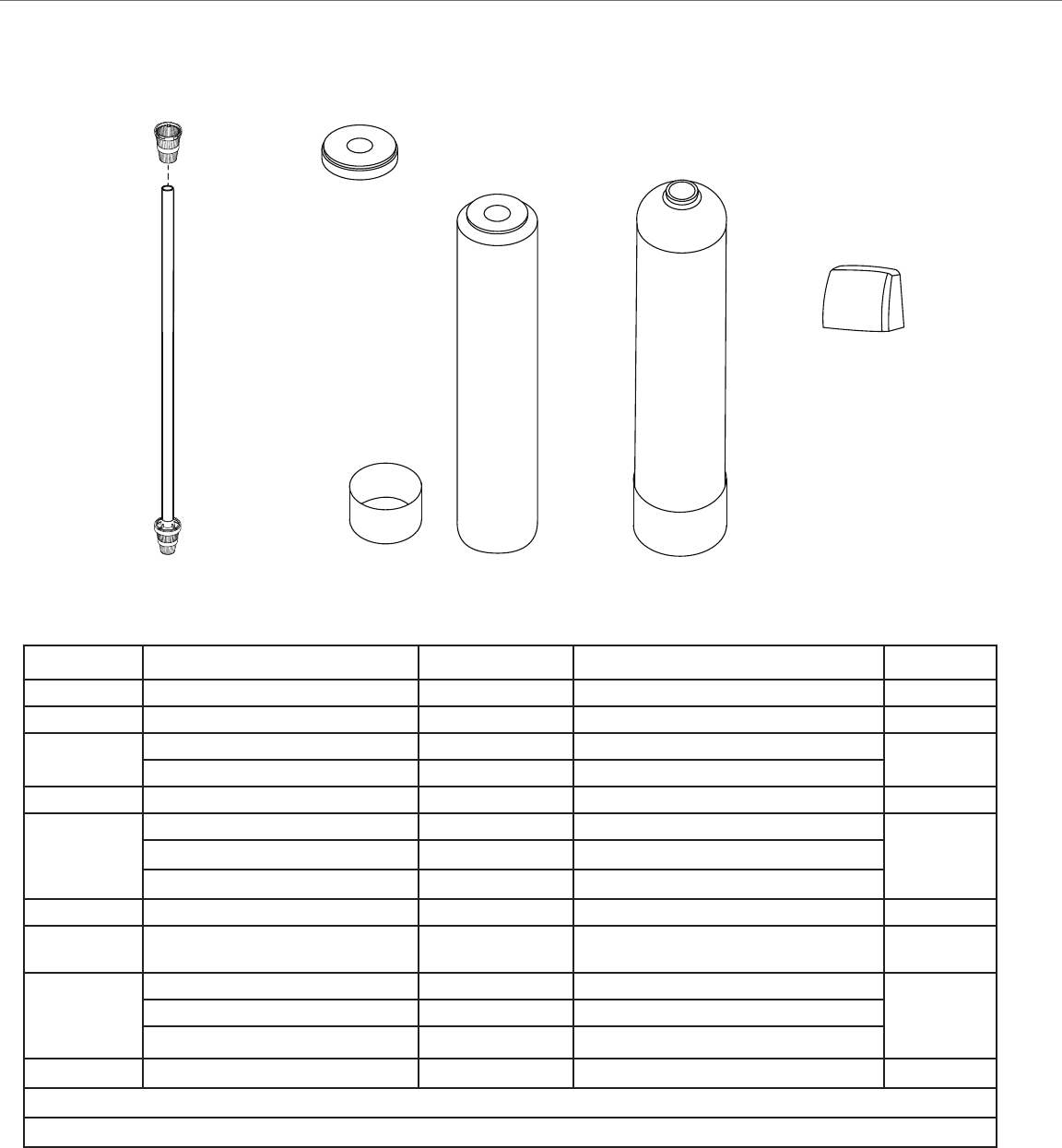
Drawing No. Part No. Mfg. Part No. Description Quantity
1 3TDD1203 Top Distributor 1
*2 3DIST10554ST Distributor Assembly 1
*3
3TJCAPGRAY Tank Jacket Cap Cool Gray 10 inch 1
3TJCAPGRAY13INCH Tank Jacket Cap Cool Gray 13 inch
*4 3TJSLEEVEMOBILGRAY Tank Jacket Sleeve 10" Mobil Gray 1
*5
3TJBM1044MOBILGRAY Tank Jacket 10 x 44 Mobil Gray
1
3TJBM1054MOBILGRAY Tank Jacket 10 x 54 Mobil Gray
3TJBM1354MOBILGRAY Tank Jacket 13 x 54 Mobil Gray
**6 3LLB-M-TJ_4.5X1.6331 Tank Jacket Label 1
* **7 3TJBMFOAMSTRIP25FT Foam strips for Tank Jacket
(Length varies by Model)
*8
3MT1044PK12 Mineral Tank 10 x 44
1
3MT1054PK12 Mineral Tank 10 x 54
3MT1354PK12 Mineral Tank 13 x 54
9 3CVWTHRCVR-LD-COOLGRAY Mid Size Weather Cover Cool Gray 1
* Varies by Model
9
Figure 28
4
Mineral Tank Assembly, Valve Cover, and Parts List
39
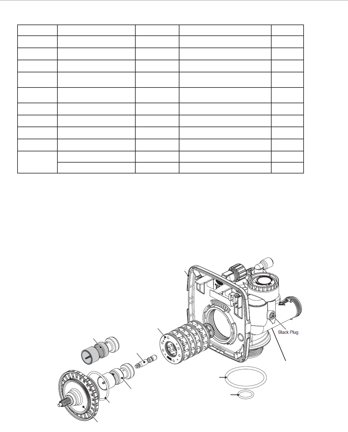
Drawing No. Part No. Mfg Part No. Description Quantity
1 3CVSPACERSTACKV3005 V3005 Spacer Stack Assembly 1
2 3CVDRIVECAPASYV3004 V3004 Drive Cap Assembly 1
3 V3496 Drive Back Plate 1
4a 3CVPISTONDWNFLOW3011 V3011
(solid amber color)
1
4b 3CVPISTONUPFLOW30110 V3011-01
(black & amber color)
1
5 3CVPISTONREGENV3174 V3174 Regenerant Piston 1
6 V3135 O-Ring 228 1
7 3CVTNKADPTORINGV3180 V3180 O-Ring 337 1
8 3CVBPFTG ORINGV3105 V3105 O-Ring 215 (Distributor Tube) 1
9 V3001 1
V3001UP 1
NOTE: V3004 drive cap assembly includes o-ring 228
9
3
9
4a
4b
1
6
2
5
7
8
Figure 29
Drive Cap, Piston, Regenerant Piston and Stacker Assembly
Control Valve - Drive Cap, Piston, Regenerant Piston, and Stacker Assembly
40
and 013 (upper) o-ring.
NOTE:
located in the UP hole and injector plug is in the other hole.
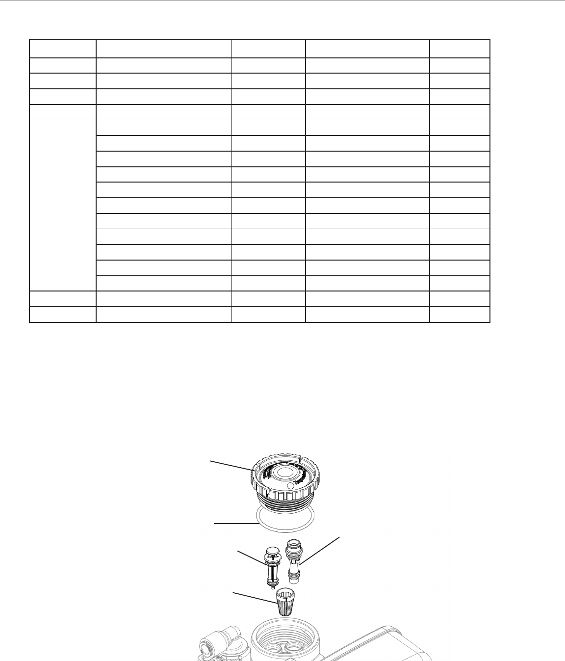
Drawing No. Part No. Mfg Part No. Description Quantity
1 3CVINJCAPV3176 V3176 Injector Cap 1
2 3CVORINGINJBPV3152 V3152 O-Ring 135 1
3 3CVINJSCREENV3177-01 V3177-01 Injector Screen Cage 1
4 3CVINJASYV3010-1Z V3010-1Z Injector Asy Z Plug 1
5
3CVINJASYCV3010-1A V3010-1A Injector Asy A Black 1
3CVINJASYCV3010-1B V3010-1B 1
3CVINJASYCV3010-1C V3010-1C Injector Asy C Violet 1
3CVINJASYCV3010-1D V3010-1D Injector Asy D Red 1
3CVINJASYEV3010-1E V3010-1E Injector Asy E White 1
3CVINJASYFV3010-1F V3010-1F Injector Asy F Blue 1
3CVINJASYGV3010-1G V3010-1G 1
3CVINJASYHV3010-1H V3010-1H Injector Asy H Green 1
3CVINJASYIV3010-1I V3010-1I Injector Asy I Orange 1
3CVINJASYJV3010-1J V3010-1J Injector Asy J Light Blue 1
3CVINJASYCV3010-1K V3010-1K Injector Asy K Light Green 1
V3170 O-Ring 011 *
V3171 O-Ring 013 *
1
2
3
4
5
Figure 30
Control Valve - Injector Cap and Injector
41
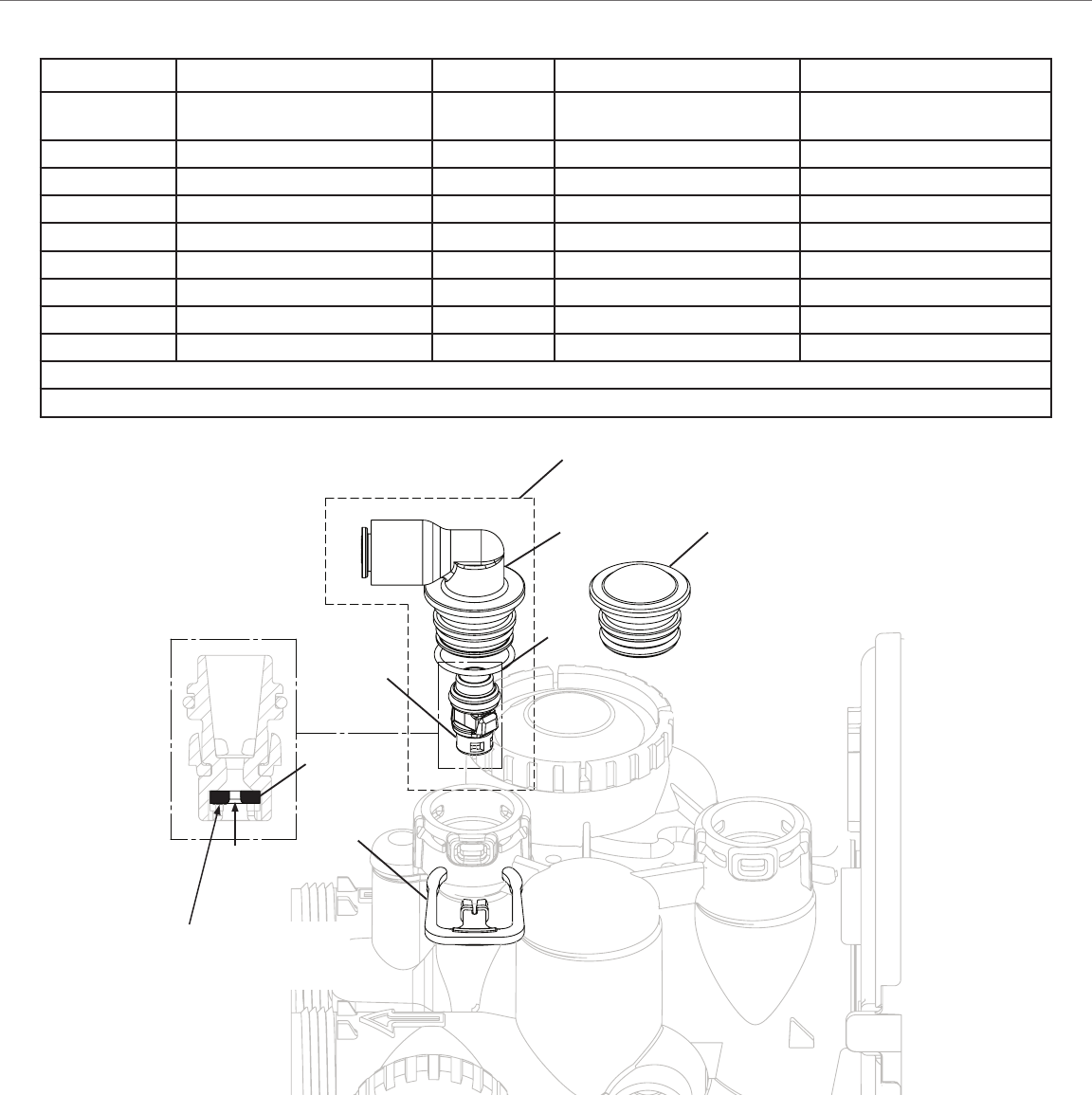
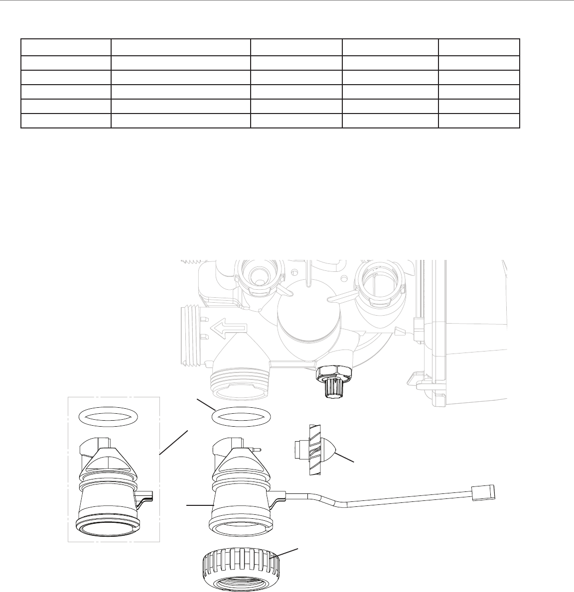
Drawing No. Part No. Mfg. Part No. Description Quantity
1 3CVREFILLPORTPLUGASY V3195-01 This part is required for back
2 3CVLOCKINGCLIPH4615 H4615 1
3 H4628 1
4 3CVELBOWORINGV3163 V3163 O-Ring 019 1
5 3CVRETAINERASYV3165 V3165-01* RFC Retainer Asy (0.5 gpm) *
6 V3182 1
7 V3330-01 1
** V3552 Option
** H4650 Option
Rell Flow Control Assembly and Rell Port Plug
Water
Flow
Proper RFC orientation
directs refi ll water fl ow
towards the washer face
with rounded edge and text.
Figure 31
Drawing No. Part No. Mfg. Part No. Description Quantity
1 3CVREFILLPORTPLUGASY V3195-01 This part is required for back
2 3CVLOCKINGCLIPH4615 H4615 1
3 H4628 1
4 3CVELBOWORINGV3163 V3163 O-Ring 019 1
5 3CVRETAINERASYV3165 V3165-01* RFC Retainer Asy (0.5 gpm) *
6 V3182 1
7 V3330-01 1
** V3552 Option
** H4650 Option
7
3 1
4
5
6
2
42
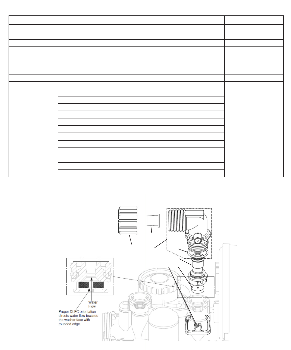
Drawing No. Part No. Mfg. Part No. Description Quantity
1 3CVLOCKINGCLIPH4615 H4615 1
2 PKP10TS8-Bulk Option
3 V3192 Option
4* V3158-01 1
4* 3CVDRAINELBOWNOSILEN V3158-02
Silencer
1
5 3CVELBOWORINGV3163 V3163 O-Ring 019 1
6* 3CVDLFCRETAINERASY V3159-01 DLFC Retainer Asy 1
7
V3162-007 DFLC 0.7 gpm for ¾
One DLFC must be used if
V3162-010 DFLC 1.0 gpm for ¾
V3162-013 DFLC 1.3 gpm for ¾
V3162-017 DFLC 1.7 gpm for ¾
3CVDLFC022 V3162-022 V3162-022 DFLC 2.2 gpm for ¾
3CVDLFC027 V3162-027 V3162-027 DFLC 2.7 gpm for ¾
3CVDLFC032 V3162-032 V3162-032 DFLC 3.2 gpm for ¾
3CVDLFC042 V3162-042 V3162-042 DFLC 4.2 gpm for ¾
3CVDLFC053 V3162-053 V3162-053 DFLC 5.3 gpm for ¾
3CVDLFC065 V3162-065 V3162-065 DFLC 6.5 gpm for ¾
3CVDLFC075 V3162-075 V3162-075 DFLC 7.5 gpm for ¾
3CVDLFC090 V3162-090 V3162-090 DFLC 9.0 gpm for ¾
3CVDLFC100 V3162-100 V3162-100 DFLC 10.0 gpm for ¾
Figure 32
3
2
4
5
7
6
1
Drain Line Flow Control Assembly
43
*Order number V3003 includes V3118-01 Turbine Asy and V3105 O-Ring 215.
Drawing No. Part No. Mfg. Part No. Description Quantity
1 3CVBPFTG NUT1INV3151 V3151 Nut 1”QC 1
2 3CVMETERASYV3003 V3003* Meter ASY 1
3 3CVTURBINEASYV311801 V3118-01 Turbine ASY 1
4 3CVBPFTG ORINGV3105 V3105 O-Ring 215 1
5 3CVMETERPLUG300301 V3003-01 Meter Plug ASY 1
Water Meter, Meter Plug, and Mixing Valve
Figure 33
5
4
2
1
3

44
OFF
OFF
OFF
OFF
Figure 34
1
2
3
4
5
6
7
8
9
10
Drawing No. Part No. Mfg. Part No. Description Quantity
3CVBYPASSV3006 V3006 Bypass Assembly 1
1 3CVBPFTG NUT1INV3151 V3151 Nut 1" (2.54 cm) Quick Connect (QC) 2
2 3CVBPFTG RINGV3150 V3150 Split Ring 2
3 3CVBPFTG ORINGV3105 V3105 O-Ring 215 2
4 V3145 Bypass 1" (2.54 cm) Rotor 2
5 V3146 Bypass Cap 2
6 V3147 Bypass Handle 2
7 V3148 Bypass Rotor Seal Retainer 2
8 3CVORINGINJBPV3152 V3152 O-Ring 135 2
9 V3155 O-Ring 112 2
10 V3156 O-Ring 214 2
Bypass Valve
45
Figure 35
1
2
3
4
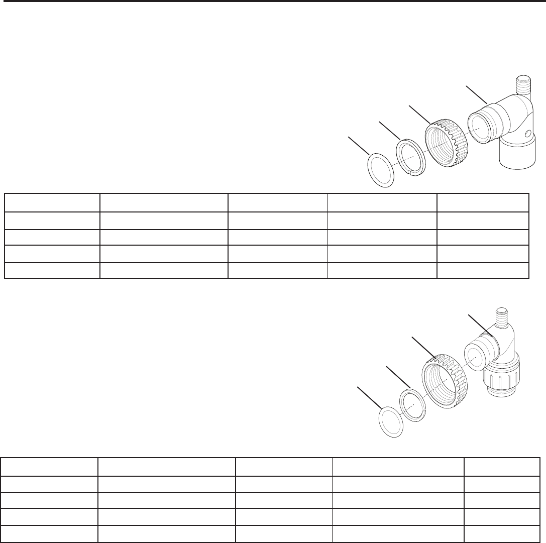
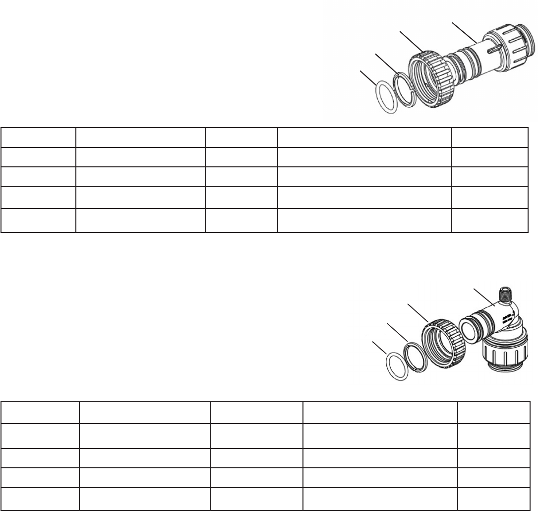
Drawing No. Part No. Mfg. Part No. Description Quantity
1 3CVBPFTG NUT1INV3151 V3151 Nut 1" (2.54 cm) QC 2
2 3CVBPFTG RINGV3150 V3150 Split Ring 2
3 3CVBPFTG ORINGV3105 V3105 O-Ring 215 2
4 V3189 2
Order No.: 3CVBPFTGV3007-01
Description:
Figure 36
1
2
3
4
Drawing No. Part No. Mfg. Part No. Description Quantity
1 3CVBPFTG NUT1INV3151 V3151 Nut 1" (2.54 cm) QC 2
2 3CVBPFTG RINGV3150 V3150 Split Ring 2
3 3CVBPFTG ORINGV3105 V3105 O-Ring 215 2
4 V3790 2
Order No.: 3CVBPFTGV3007-15
Description:
®
QC 90° Assembly
BYPASS FITTING PACKAGES
Bypass Fitting Packages
46
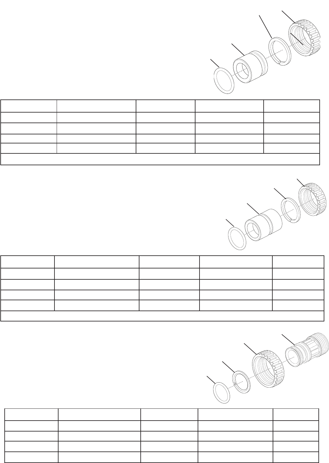
Order No.: 3CVBPFTGV3007-03
Description:
Figure 37
2
4
3
1
Drawing No. Part No. Mfg. Part No. Description Quantity
1 3CVBPFTG NUT1INV3151 V3151 Nut 1" (2.54 cm) QC 2
2 3CVBPFTG RINGV3150 V3150 Split Ring 2
3 3CVBPFTG ORINGV3105 V3105 O-Ring 215 2
4 V3188-01LF 2
Do not install in California
Bypass Fitting Packages
Order No.: 3CVBPFTGV3007-02
Description:
Figure 38
2
4
3
1
Drawing No. Part No. Mfg. Part No. Description Quantity
1 3CVBPFTG NUT1INV3151 V3151 Nut 1" (2.54 cm) QC 2
2 3CVBPFTG RINGV3150 V3150 Split Ring 2
3 3CVBPFTG ORINGV3105 V3105 O-Ring 215 2
4 V3188-LF 2
Do not install in California
Order No.: 3CVBPFTGV007-04
Description: Fitting 1” (2.54 cm) Male MPT Assembly
Figure 39
1
2
3
4
Drawing No. Part No. Mfg. Part No. Description Quantity
1 3CVBPFTG NUT1INV3151 V3151 Nut 1" (2.54 cm) QC 2
2 3CVBPFTG RINGV3150 V3150 Split Ring 2
3 3CVBPFTG ORINGV3105 V3105 O-Ring 215 2
4 V3164 1" Male MPT 2

47
Bypass Fitting Packages
1
2
3
4
1
2
3
4
Figure 42
Figure 41
Drawing No. Part No. Mfg. Part No. Description Quantity
1 3CVBPFTG NUT1INV3151 V3151 Nut 1" (2.54 cm) QC 2
2 3CVBPFTG RINGV3150 V3150 Split Ring 2
3 3CVBPFTG ORINGV3105 V3105 O-Ring 215 2
4 V3629-LF 1" Brass SharkBite
®
LF 2
Order No.: 3CVBPFTG1.0V3007-13
Description: Fitting 1” (2.54 cm) Brass SharkBite
®
Assembly LF
Drawing No. Part No. Mfg. Part No. Description Quantity
1 3CVBPFTG NUT1INV3151 V3151 Nut 1" (2.54 cm) QC 2
2 3CVBPFTG RINGV3150 V3150 Split Ring 2
3 3CVBPFTG ORINGV3105 V3105 O-Ring 215 2
4 V3191 Bypass Vertical Adapter 2
Order No.: 3CVBPFTGV3191-01
Description: Fitting Bypass Vertical Adapter Assembly
Drawing No. Part No. Mfg. Part No. Description Quantity
1 3CVBPFTG NUT1INV3151 V3151 Nut 1" (2.54 cm) QC 2
2 3CVBPFTG RINGV3150 V3150 Split Ring 2
3 3CVBPFTG ORINGV3105 V3105 O-Ring 215 2
4 V3628-LF
®
Assembly LF 2
Order No.: 3CVBPFTGV3007-12
Description:
®
Assembly LF
1
2
3
4
Figure 40
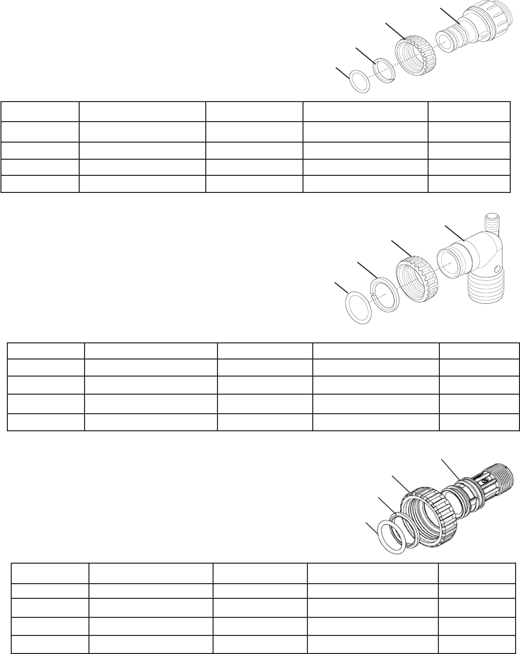
48
Order No.: 3CVBPFTGV3007-17
Description: Fitting 1” (2.54 cm) John Guest
®
QC Assembly
Figure 43
1
2
3
4
Drawing No. Part No. Mfg. Part No. Description Quantity
1 3CVBPFTG NUT1INV3151 V3151 Nut 1" (2.54 cm) QC 2
2 3CVBPFTG RINGV3150 V3150 Split Ring 2
3 3CVBPFTG ORINGV3105 V3105 O-Ring 215 2
4 V4045 1" John Guest
®
QC ASY 2
Bypass Fitting Packages
Figure 44
1
2
4
Drawing No. Part No. Mfg. Part No. Description Quantity
1 3CVBPFTG NUT1INV3151 V3151 Nut 1" (2.54 cm) QC 2
2 3CVBPFTG RINGV3150 V3150 Split Ring 2
3 3CVBPFTG ORINGV3105 V3105 O-Ring 215 2
4 V3149 2
Order No.: 3CVBPFTGV3007-00
Description:
Order No.: 3CVBPFTGV3007-18
Description:
1
2
3
4
Drawing No. Part No. Mfg. Part No. Description Quantity
1 3CVBPFTG NUT1INV3151 V3151 Nut 1" (2.54 cm) QC 2
2 3CVBPFTG RINGV3150 V3150 Split Ring 2
3 3CVBPFTG ORINGV3105 V3105 O-Ring 215 2
4 V4232 2
3
Figure 45
49
Drawing No. Part No. Mfg. Part No. Description Quantity
1
3CVBPFTG NUT1INV3151
V3151
Nut 1" (2.54 cm) QC
2
2
3CVBPFTG RINGV3150
V3150
Split Ring
2
3
3CVBPFTG ORINGV3105
V3105
O-Ring 215
2
4
V3149
2
Drawing No. Part No. Mfg. Part No. Description Quantity
1 3CVBPFTG NUT1INV3151 V3151 Nut 1" (2.54 cm) QC 2
2 3CVBPFTG RINGV3150 V3150 Split Ring 2
3 3CVBPFTG ORINGV3105 V3105 O-Ring 215 2
4 V4317 2
Order No.: 3CVBPFTGV3007-20
Description: Fitting 1" (2.54 cm) John Guest
®
Figure 47
1
2
3
4
1
2
3
4
Order No.: 3CVBPFTGV3007-19
Description:
®
Straight QC Assembly
Figure 46
Drawing No. Part No. Mfg. Part No. Description Quantity
1 3CVBPFTG NUT1INV3151 V3151 Nut 1" (2.54 cm) QC 2
2 3CVBPFTG RINGV3150 V3150 Split Ring 2
3 3CVBPFTG ORINGV3105 V3105 O-Ring 215 2
4 V4223 2
Bypass Fitting Packages

50
Problem Possible Cause Solution
No Display on PC Board 1.
2.
end not connected to PC board
connection
3.
4.
5. . Defective PC Board)
1.
2.
cord end to PC Board connection
3. Verify proper voltage is being delivered to PC
Board
4.
5. Replace PC Board
PC Board does not display
correct time of day
1.
2.
tripped GFI
3.
4. Defective PC Board
1. Use uninterrupted outlet
2.
3. Reset time of day. If PC Board has battery back
up present the battery may be depleted. Refer to
4. Replace PC Board
Display does not indicate that
1. Bypass valve in bypass position
2. Meter is not connected to meter
connection on PC Board
3.
4.
into three pin connector
5. Defective meter
6. Defective PC Board
1. Turn bypass handles to place bypass in service
position
2. Connect meter to three pin connection labeled
METER on PC board
3. Remove meter and check for rotation or foreign
material
4.
into three pin connector labeled METER
5. Replace meter
6. Replace PC Board
Control valve regenerates
1.
2. Time of day not set correctly
3. Time of regeneration set incorrectly
4. Control valve set at “on 0”
(immediate regeneration)
5. Control valve set at “NORMAL + on
1. Reset time of day. If PC Board has battery
back up present the battery may be depleted.
Refer to battery replacement for instructions.
2. Reset to correct time of day
3. Reset regeneration time
4. Check programming setting and reset to
NORMAL (for a delayed regen time)
5. Check programming setting and reset
to NORMAL (for a delayed regen time)
Reset time of day. If PC Board has battery
back up present the battery may be depleted.
Refer to battery replacement for instructions.
TROUBLESHOOTING

51
Problem Possible Cause Solution
Timer does not display correct
time of day
1.
2.
3. Defective PC board
1. Use uninterrupted outlet
2. Transformer unplugged
3. Replace PC board
Timer does not display time of day 1. Transformer unplugged
2.
3. Defective transformer
4. Defective PC board
1.
2.
3. Replace transformer
4. Replace PC board
Control valve does not regenerate
button (s) is depressed and held.
For TC valves the buttons are
button is REGEN
1. Broken drive gear or drive cap
assembly
2. Broken Piston Rod
3. Defective PC Board
1. Replace drive gear or drive cap
assembly
2. Replace piston rod
3. Defective PC Board
Control valve does not regenerate
correct button (s) is depressed and
held. For TC valves the buttons
are
button is REGEN
1. Bypass valve in bypass position
2. Meter is not connected to meter
connection on PC Board
3.
4. Incorrect programming
5.
three pin connector
6. Defective meter
7. Defective PC Board
1. Turn bypass handles to place bypass
in service position
2. Connect meter to three pin connection
labeled METER on PC Board
3. Remove meter and check for rotation
or foreign material
4. Check for programming error
5.
securely into three pin connector
labeled METER
6. Replace meter
7. Replace PC Board
delivered
1. Bypass valve is open or faulty
2. Media is exhausted due to high
usage
3. Meter not registering
4.
5.-
erant
in regenerant tank
6.
7.
regenerant
tank
1. Fully close bypass valve or replace
2. Check program settings or diagnostics
3. Remove meter and check for
rotation or foreign material
4.
accordingly
5. Add proper regenerant to tank
6. Refer to Trouble Shooting Guide
7.
or debris and clean or replace

52
Problem Possible Cause Solution
Control valve uses too much
regenerant
1.
2. Improper program settings
3. Control valve regenerates frequently
1.
2. Check program setting to make sure
and application needs
3.
exhausting capacity or system is
undersized
Residual regenerant being
delivered to service
1.
2. Incorrect injector size
3. Restricted drain line
1.
minimum of 25 psi
2.
the application
3. Check drain line for restrictions or
debris and clean
1. Improper program settings
2. Plugged injector
3. Drive cap assembly not tightened in
properly
4.
5. Restricted or kinked drain line
6.
7.
1.
2. Remove injector and clean or replace
3. Re-tighten the drive cap assembly
4.
5. Check drain line for restrictions or
debris and or un-kink drain line
6.
clean or replace
7.
1. Injector is plugged
2. Faulty regenerant piston
3. Regenerant line connection leak
4. Drain line restriction of debris cause
excess back pressure
5. Drain line too long or too high
6.
1. Remove injector and clean or replace
2. Replace regenerant piston
3. Inspect regenerant line for air leak
4. Inspect drain line and clean to correct
restriction
5. Shorten length and or height
6.
pressure must remain at minimum of
20 psi (1.38 bar)
Water running to drain 1.
2.
3. Piston assembly failure
4. Drive cap assembly not tightened
in properly
1.
Reset time of day.
2.
3. Replace piston assembly
4. Re-tighten the drive cap assembly

53
Problem Possible Cause Solution
Err – 101 = Control unable to
sense motor movement
1. Motor not inserted full to engage pinion,
2. PC Board not properly snapped into drive
bracket
3. Missing reduction gears
1.
is fully engaged, check for broken
connection on the PC Board labeled
MOTOR. Press NEXT and REGEN
buttons for 3 seconds to
from PC Board for 5 seconds and
then reconnect
2. Properly snap PC Board into drive
bracket and then Press NEXT and
REGEN buttons for 3 seconds to
from PC Board for 5 seconds and
then reconnect
3. Replace missing gears
Err – 102 = Control valve motor ran
the next cycle position and stalled
1. Foreign material is lodged in control valve
2. Mechanical binding
3. Main drive gear too tight
4. Improper voltage being delivered to
PC Board
1. Open up control valve and pull out
assembly for inspection. Press NEXT
and REGEN buttons for 3 seconds to
from PC Board for 5 seconds and
then reconnect
2.
assembly, check reduction gears,
check drive bracket and main drive
gear interface. Press NEXT and
REGEN buttons for 3 seconds to
from PC Board for 5 seconds and
then reconnect
3. Loosen main drive gear. Press NEXT
and REGEN buttons for 3 seconds to
from PC Board for 5 seconds and
then reconnect
4. Verify that proper voltage is being
supplied. Press NEXT and REGEN
buttons for 3 seconds to resynchro-
Board for 5 seconds and then
reconnect

54
Problem Possible Cause Solution
Err – 103 = Control
valve motor ran too long
next cycle position
1. Motor failure during a regeneration
2. Foreign matter built up on piston and
stack assemblies creating friction and
drag enough to time out motor
3. Drive bracket not snapped in properly
and out enough that reduction gears
and drive gear do not interface
1. Check motor connections then press NEXT and
REGEN buttons for 3 seconds to resynchronize
supply from PC board for 5 seconds and then
reconnect
2. Replace piston and stack assemblies. Press NEXT
and REGEN buttons for 3 seconds to resynchronize
supply from PC Board for 5 seconds and then
reconnect
3. Snap drive bracket in properly then press NEXT
and REGEN buttons for 3 seconds to resynchronize
supply from PC board for 5 seconds and then
reconnect
Err – 104 = Control valve
motor ran too long and
timed out trying to reach
home position
Drive bracket not snapped in properly
and out enough that reduction gears and
drive gear do not interface
Snap drive bracket in properly then press NEXT and
REGEN buttons for 3 seconds to resynchronize
supply from PC board for 5 seconds and then
reconnect
Err – 106, Err - 116 =
AUX MAV valve motor ran
the proper park position
Motorized Alternating
Valve = MAV
Separate Source =SEPS
No Hard Water Bypass =
NHBP
Auxiliary MAV = AUX MAV
1. Control valve programmed for ALT A
out having a MAV or NHBP valve
attached to operate that function
2.
to PC Board
3.
4. Foreign matter built up on piston and
stack assemblies creating friction and
drag enough to time out motor
1. Press NEXT and REGEN buttons for 3 seconds
seconds and then reconnect. Then re-program
valve to proper setting
2.
connection labeled DRIVE. Press NEXT and
REGEN buttons for 3 seconds to resynchronize
supply from PC Board for 5 seconds and then
reconnect
3. Properly insert motor into casing, do not force into
casing Press NEXT and REGEN buttons for 3
Board for 5 seconds and then reconnect
4. Replace piston and stack assemblies. Press
NEXT and REGEN buttons for 3 seconds to
seconds and then reconnect
valve motor ran too short
proper park position
Motorized Alternating
Valve = MAV
Separate Source = SEPS\
No Hard Water Bypass =
NHBP
Auxiliary MAV = AUX MAV
1.
NHBP valve
2. Mechanical binding
1.
NEXT and REGEN buttons for 3 seconds to
seconds and then reconnect
2.
reduction gears, drive gear interface, and check
jammed into motor body. Press NEXT and REGEN
from PC Board for 5 seconds and then reconnect

55
Error Code Description of Error
101 Valve Motor Output Energized - NOT SENSING VALVE MOVEMENT - perform soft reset to clear
102
to regen to be sure obstruction is clear
103
104 Valve Motor UNABLE TO FIND HOME POSITION - during regeneration or control reset - perform soft reset to clear
106
107
perform soft reset to clear
109
by the micro-controller - perform soft reset to clear
116
56
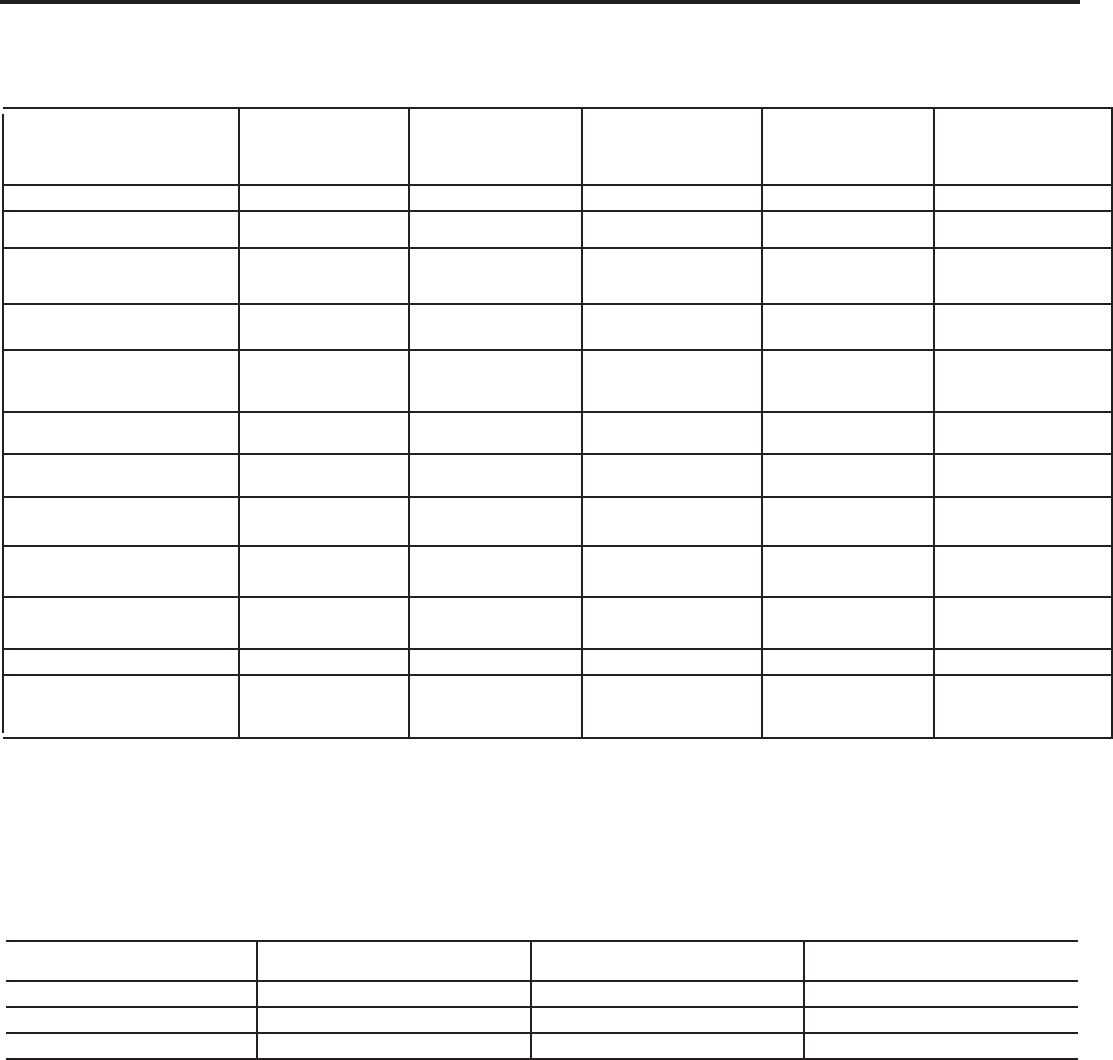
PERFORMANCE DATA SHEET
Model Numbers
*
***
3M-ST32-XXX
*
***
3M-ST40-XXX
*
****
3M-ST48-XXX
*
***
3M-ST64-XXX
*
***
3M-ST80-XXX
9.0 gpm 10.0 gpm 13.0 gpm 15.0 gpm 15.0 gpm
8 psi 9 psi 15 psi 15 psi 15 psi
15.9 gpm @ 15 psi
18.2 gpm @ 20 psi
22.4 gpm @ 25 psi
16.2 gpm @15 psi
19.2 gpm @ 20 psi
22.0 gpm @ 25 psi
17.7 gpm @ 15 psi
21.1 gpm @ 20 psi
24.0 gpm @ 25 psi
20.0 gpm @ 15 psi
23.5 gpm @ 20 psi
26.6 gpm @ 25 psi
14.5 gpm @ 15 psi
17.3 gpm @ 20 psi
19.8 gpm @ 25 psi
Electrical Requirements
Input: 100V-120V ~
Input: 100V-120V ~
Input: 100V-120V ~
Input: 100V-120V ~
Input: 100V-120V ~
23,500 @ Std (9.0lbs)
28,000 @ High (15.0lbs)
29,375 @ Std (11.3lbs)
35,500 @ High (18.8lbs)
35,250 @ Std (13.5lbs)
42,000 @ High (22.5lbs)
48,000 @ Std (18.0lbs)
56,000 @ High (30.0lbs)
58,750 @ Std (22.5lbs)
70,000 @ High (37.5lbs)
Type and amount of Ion Exchange
resin
Premium Cation
1.0 cu ft
Premium Cation
1.25 cu ft
Premium Cation
1.5 cu ft
Premium Cation
2.0 cu ft
Premium Cation
2.5 cu ft
Working Water Pressure
20 to 120 psi
20 to 120 psi
20 to 120 psi
20 to 120 psi
20 to 120 psi
35 to 100°F
(1.7 to 37.8°C)
35 to 100°F
(1.7 to 37.8°C)
35 to 100°F
(1.7 to 37.8°C)
35 to 100°F
(1.7 to 37.8°C)
35 to 100°F
(1.7 to 37.8°C)
to drain during regeneration
salt setting
18,200 grains 22,750 grains 27,300 grains 36,400 grains 45,500 grains
Accepted type or grade, pellet or
Sodium Chloride Sodium Chloride Sodium Chloride Sodium Chloride Sodium Chloride
International Plumbing Code (IPC) and International Residential Code (IRC).
Substance Reduction Requirement Average% Reduction
Chlorine >50% reduction 89.9%
Barium
exchange per pound of salt (based on NaCl equivalency) (477 grams of total hardness exchanged per kilogram of
standard laboratory conditions, actual performance can vary.
Refer to the system installation and operations manual for set-up and programming instructions.
operations manual for user responsibility, parts and service availability, any further restrictions or limitations to the
use of this product.
MAYTAG
®
WATER TREATMENT SYSTEM
57
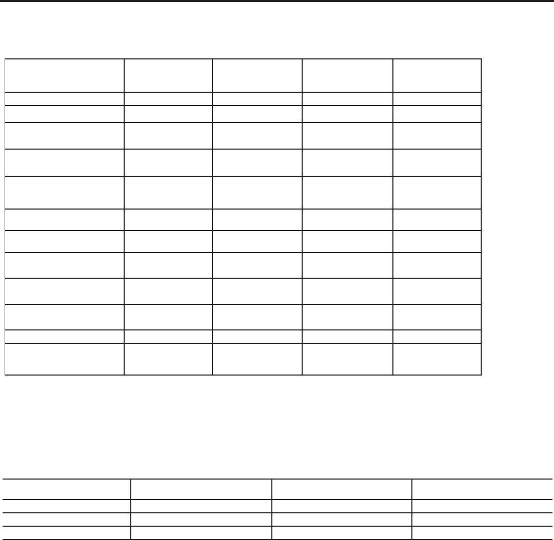
PERFORMANCE DATA SHEET
Model Numbers
*
***
3M-ST32-XXX
*
***
3M-ST40-XXX
*
****
3M-ST48-XXX
*
***
3M-ST64-XXX
*
***
3M-ST80-XXX
9.0 gpm
10.0 gpm
13.0 gpm
15.0 gpm
15.0 gpm
8 psi
9 psi
15 psi
15 psi
15 psi
15.9 gpm @ 15 psi
18.2 gpm @ 20 psi
22.4 gpm @ 25 psi
16.2 gpm @15 psi
19.2 gpm @ 20 psi
22.0 gpm @ 25 psi
17.7 gpm @ 15 psi
21.1 gpm @ 20 psi
24.0 gpm @ 25 psi
20.0 gpm @ 15 psi
23.5 gpm @ 20 psi
26.6 gpm @ 25 psi
14.5 gpm @ 15 psi
17.3 gpm @ 20 psi
19.8 gpm @ 25 psi
Electrical Requirements
Input: 100V-120V ~
Input: 100V-120V ~
Input: 100V-120V ~
Input: 100V-120V ~
Input: 100V-120V ~
23,500 @ Std (9.0lbs)
28,000 @ High (15.0lbs)
29,375 @ Std (11.3lbs)
35,500 @ High (18.8lbs)
35,250 @ Std (13.5lbs)
42,000 @ High (22.5lbs)
48,000 @ Std (18.0lbs)
56,000 @ High (30.0lbs)
58,750 @ Std (22.5lbs)
70,000 @ High (37.5lbs)
Type and amount of Ion Exchange
resin
Premium Cation
1.0 cu ft
Premium Cation
1.25 cu ft
Premium Cation
1.5 cu ft
Premium Cation
2.0 cu ft
Premium Cation
2.5 cu ft
Working Water Pressure
20 to 120 psi
20 to 120 psi
20 to 120 psi
20 to 120 psi
20 to 120 psi
35 to 100°F
(1.7 to 37.8°C)
35 to 100°F
(1.7 to 37.8°C)
35 to 100°F
(1.7 to 37.8°C)
35 to 100°F
(1.7 to 37.8°C)
35 to 100°F
(1.7 to 37.8°C)
to drain during regeneration
salt setting
18,200 grains
22,750 grains
27,300 grains
36,400 grains
45,500 grains
Accepted type or grade, pellet or
Sodium Chloride
Sodium Chloride
Sodium Chloride
Sodium Chloride
Sodium Chloride
International Plumbing Code (IPC) and International Residential Code (IRC).
exchange per pound of salt (based on NaCl equivalency) (477 grams of total hardness exchanged per kilogram of
laboratory conditions, actual performance can vary.
Refer to the system installation and operations manual for set-up and programming instructions.
operations manual for user responsibility, parts and service availability, any further restrictions or limitations to the use
of this product.
MAYTAG
®
WATER TREATMENT SYSTEM
Substance Reduction Requirement Average% Reduction
Chlorine >50% reduction 89.9%
Barium
Model Numbers
*
**
***
3M-STR32-XXX
*
**
***
3M-STR32XC-XXX
*
**
***
3M-STR40-XXX
*
**
***
3M-STR64-XXX
9.0.0 gpm 10.0.0 gpm 10.0 gpm 15.0 gpm
8 psi 8 psi 9 psi 15 psi
15.9 gpm @ 15 psi
18.2 gpm @ 20 psi
22.4 gpm @ 25 psi
15.9 gpm @ 15 psi
18.2 gpm @ 20 psi
22.4 gpm @ 25 psi
15.5 gpm @15 psi
18.7 gpm @ 20 psi
21.7 gpm @ 25 psi
16.5 gpm @ 15 psi
19.8 gpm @ 20 psi
22.8 gpm @ 25 psi
Electrical Requirements
Input: 100V-120V ~
Input: 100V-120V ~
Input: 100V-120V ~
Input: 100V-120V ~
23,500 @ Std (9.0lbs)
28,000 @ High (15.0lbs)
23,500 @ Std (9.0lbs)
28,000 @ High (15.0lbs)
29,375 @ Std (11.3lbs)
35,500 @ High (18.8lbs)
48,000 @ Std (18.0lbs)
56,000 @ High (30.0lbs)
Type and amount of Ion Exchange
resin
Premium Cation
1.0 cu ft
Premium Cation
1.0 cu ft
Premium Cation
1.25 cu ft
Premium Cation
2.0 cu ft
Working Water Pressure
20 to 120 psi
20 to 120 psi
20 to 120 psi
20 to 120 psi
35 to 100°F
(1.7 to 37.8°C)
35 to 100°F
(1.7 to 37.8°C)
35 to 100°F
(1.7 to 37.8°C)
35 to 100°F
(1.7 to 37.8°C)
to drain during regeneration
salt setting
18,200 grains 18,200 grains 22,750 grains
36,400 grains
Accepted type or grade, pellet or
Sodium Chloride Sodium Chloride Sodium Chloride Sodium Chloride
58
Warranty
59
Notes
W11572554A
®
©2022 MAYTAG. All rights reserved. Manufactured under license by LeverEdge.
